
The Core Dilemma: Direct PCB Wire Soldering vs. Crimped Connectors
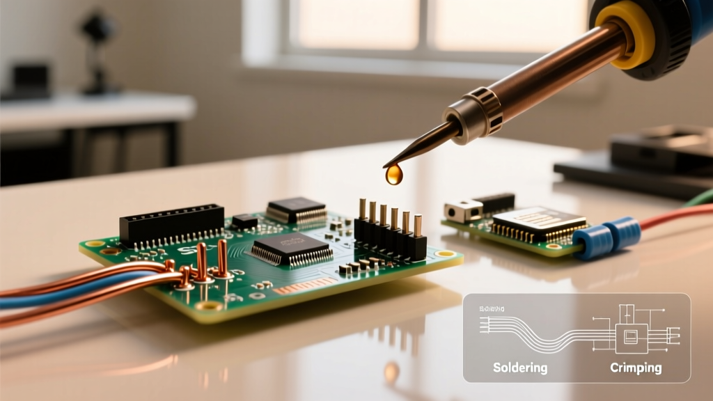
When routing external signals, power, or sensor data to a printed circuit board, engineers and DIYers face a fundamental mechanical decision: should you use direct PCB wire soldering to pads and vias, or rely on crimped wire-to-board connectors? While both methods achieve electrical continuity, their mechanical reliability, tooling costs, and failure modes diverge drastically under real-world conditions.
In 2026, with the continued miniaturization of consumer electronics and the rise of high-vibration DIY projects like FPV drones and autonomous rovers, choosing the wrong termination method can lead to catastrophic field failures. This guide provides a deep-dive technical comparison between direct soldering and crimping, complete with tooling costs, IPC standard references, and edge-case failure analysis.
Method 1: Direct PCB Wire Soldering
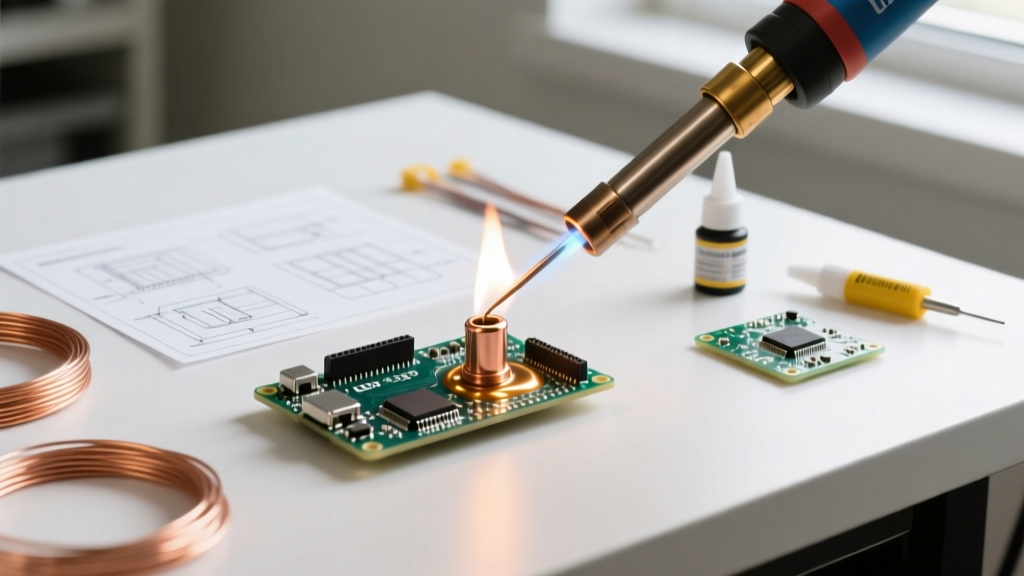
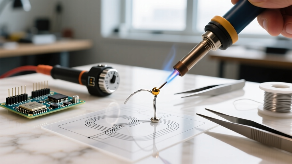
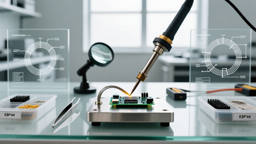
Direct soldering involves stripping a wire, tinning the exposed strands, and fusing it directly to a PCB pad, via, or plated through-hole (PTH). It is the most common method for prototyping and high-current applications where connector resistance is unacceptable.
Tooling and Material Costs
The barrier to entry for soldering is relatively low, but achieving professional-grade reliability requires precise temperature control.
- Soldering Station: A reliable digital station like the Weller WE1010NA ($105) or Hakko FX-888D ($115) is mandatory. Cheap unregulated irons cause pad delamination.
- Solder Alloy: For hand-soldering, 63/37 eutectic leaded solder (e.g., Kester 245, $35/lb) remains the gold standard due to its sharp melting point (183°C), which minimizes thermal dwell time. Lead-free SAC305 requires higher tip temperatures (350°C+), increasing the risk of lifting FR4 pads.
- Flux: Tacky flux (e.g., Amtech NC-559, $20) is essential for wetting and preventing cold joints.
Execution and IPC Standards
According to IPC-A-610 standards for wire termination, a proper soldered wire joint must exhibit a smooth, concave fillet with visible wetting. The wire should not be buried entirely in solder; the inspector must be able to verify the wire's entry into the joint. Furthermore, the solder must not wick excessively up the wire's insulation, which creates a rigid stress point.
Failure Modes and Edge Cases
Expert Warning: The most common failure in direct PCB wire soldering is not a cold joint, but mechanical fatigue. When a soldered wire is subjected to vibration, the boundary between the flexible wire and the rigid solder blob acts as a fulcrum. The copper strands eventually snap exactly at the edge of the solder fillet.
Mitigation: Always apply strain relief. For production or high-reliability DIY builds, apply a flexible UV-curable solder mask (like MG Chemicals 419D, $25) or a bead of neutral-cure silicone over the joint and the first 5mm of the wire insulation to distribute mechanical stress.
Method 2: Crimped Wire-to-Board Connections
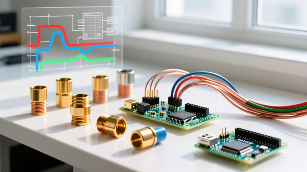
Crimping involves mechanically deforming a metal terminal around a wire's conductor and insulation, then housing it in a plastic connector (e.g., JST, Molex) that mates with a header soldered to the PCB. This modularity is the backbone of modern appliance and automotive wiring.
Tooling and Material Costs
Crimping requires highly specific tooling. Using the wrong crimper will ruin terminals and create dangerous high-resistance joints.
- Hand Crimpers: The Engineer PA-09 ($28) is exceptional for standard 2.54mm pitch JST-XH and Dupont terminals. For micro-connectors like 1.25mm Molex PicoBlade, a precision ratcheting crimper like the IWISS SN-28B ($35) is required.
- Connectors: JST-XH and Molex PicoBlade terminals cost roughly $0.03 to $0.08 each in bulk, making them highly economical for mass production, though the initial header integration requires PCB design foresight.
Execution and Mechanical Specs
A perfect crimp consists of two distinct zones: the conductor crimp (which grips the bare copper) and the insulation crimp (which grips the wire jacket for strain relief). The NASA Electronic Parts and Packaging (NEPP) program strictly mandates the presence of a "front bellmouth" and "rear bellmouth"—tiny flares in the metal terminal that prevent the crimp edges from shearing the copper strands during vibration.
Failure Modes and Edge Cases
The primary failure mode in crimping is under-crimping, where the terminal is not compressed enough, leading to wire pull-out under minimal tension. Conversely, over-crimping crushes the copper strands, reducing the effective wire gauge and creating a localized hot-spot under high current. A properly crimped 24 AWG wire in a JST-XH terminal should withstand a pull-force exceeding 15 lbs (66 Newtons) before the wire breaks.
Head-to-Head Comparison Matrix
| Feature | Direct PCB Wire Soldering | Crimped Connectors |
|---|---|---|
| Initial Tooling Cost | Low to Medium ($100 - $150) | Medium ($60 - $120 for quality ratcheting crimpers) |
| Consumable Cost per Joint | Extremely Low (< $0.02 for solder/flux) | Low to Medium ($0.05 - $0.15 for terminal + housing) |
| Vibration Resistance | Poor (without added strain relief) | Excellent (mechanical grip + insulation crimp) |
| High-Current Capacity | Excellent (direct copper-to-copper fusion) | Moderate (limited by terminal contact resistance) |
| Reworkability | Difficult (risk of pad lift upon desoldering) | Excellent (simply unplug or extract terminal) |
| PCB Real Estate | Minimal (can use tiny test points or vias) | Moderate to High (requires mating header footprint) |
Application-Specific Decision Framework
Choosing between PCB wire soldering and crimping should be dictated by the physical environment and electrical requirements of your project.
When to Choose Direct Soldering
- High-Current Power Delivery: For applications like ESC (Electronic Speed Controller) connections in drones or battery management systems (BMS) carrying 30A to 100A+, direct soldering to massive copper pours or XT60/XT90 pigtails is mandatory. Connectors introduce contact resistance that can melt under sustained high amperage.
- Space-Constrained Wearables: When designing ultra-compact PCBs where a 2.54mm JST header would consume 20% of the board area, soldering 30 AWG magnet wire directly to 0402-sized pads or micro-vias is the only viable option.
- Permanent Sealed Assemblies: If the final product will be entirely potted in epoxy or conformal coated, the reworkability of connectors is wasted, making direct soldering the more cost-effective choice.
When to Choose Crimped Connectors
- High-Vibration Environments: Automotive dashboards, RC cars, and industrial robotics subject wires to constant high-frequency shaking. The insulation crimp on a Molex or JST terminal absorbs this kinetic energy, preventing the metal fatigue that snaps soldered wires.
- Modular Prototyping & Manufacturing: If you are building a system where sensors or displays need to be swapped, replaced, or upgraded in the field, crimped wire-to-board connectors are non-negotiable. Desoldering wires in the field is impractical and risky.
- Multi-Wire Harnesses: When routing 10+ signal wires to a single PCB, crimping them into a single polarized housing prevents reverse-polarity plugging and drastically reduces assembly time compared to soldering and heat-shrinking individual wires.
Frequently Asked Questions
Can I crimp a wire and then solder the crimped terminal to the PCB?
No. This is a severe violation of manufacturer application guidelines and IPC standards. Soldering a crimped terminal alters the mechanical compression, causes flux to wick under the insulation crimp (leading to corrosion), and creates a brittle joint. Use either a solder cup terminal or a standard crimp terminal inserted into a PCB header.
What is the best wire gauge for JST-XH connectors?
JST-XH terminals are optimized for 22 AWG to 28 AWG stranded wire. The sweet spot for maximum pull-force retention and ease of crimping with standard hand tools like the Engineer PA-09 is 24 AWG or 26 AWG silicone-jacketed wire.
How do I prevent pad lifting when soldering heavy wires to a PCB?
Heavy wires (e.g., 12 AWG or 14 AWG) act as massive heat sinks, forcing you to apply the soldering iron for too long, which melts the FR4 adhesive and lifts the copper pad. To prevent this, pre-tin both the wire and the pad with a high-activity flux. Use a chisel tip set to 380°C to transfer heat rapidly, aiming for a maximum dwell time of 3 seconds. Always route the wire through a plated through-hole (PTH) for mechanical anchoring before soldering, rather than relying solely on a surface mount pad.