
The Physics of Copper: Why It Fights Back
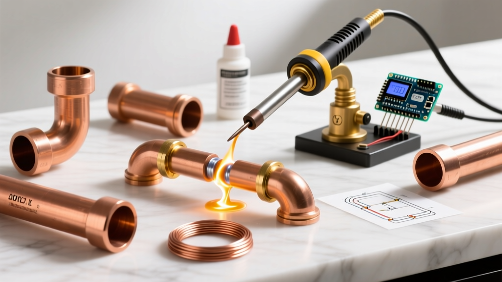
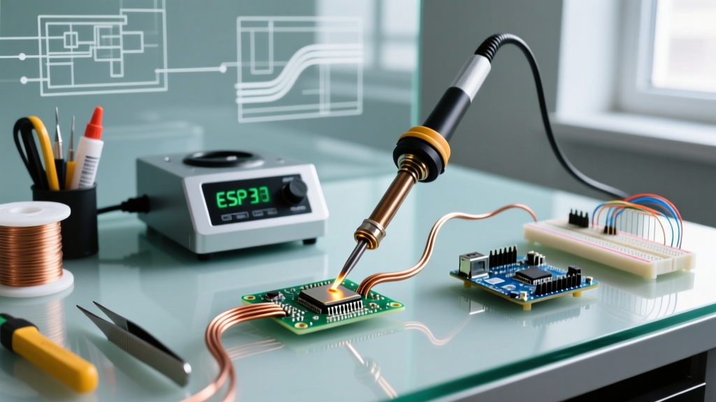
Copper is the undisputed backbone of modern electronics, prized for its exceptional electrical conductivity. However, that same physical property makes copper soldering a notorious challenge for both hobbyists and professionals. Copper boasts a thermal conductivity of approximately 401 W/(m·K)—roughly eight times higher than steel. When you apply a soldering iron to a copper pad or wire, the metal acts as a massive heat sink, rapidly pulling thermal energy away from the joint and preventing the solder alloy from reaching its liquidus state.
Furthermore, bare copper oxidizes aggressively when exposed to atmospheric oxygen and high temperatures, forming a layer of cupric oxide (CuO) that solder simply will not wet. In this comprehensive FAQ and troubleshooting guide, we dissect the most common copper soldering failures and provide exact, actionable solutions utilizing modern 2026 soldering standards.
Diagnostic Matrix: Why Your Solder Isn't Sticking
Before adjusting your temperature dial, you must accurately diagnose the failure mode. According to the IPC J-STD-001 standards for soldered electrical assemblies, distinguishing between non-wetting and dewetting is critical for root-cause analysis.
| Symptom Observed | Technical Diagnosis | Corrective Action |
|---|---|---|
| Solder forms a tight ball and rolls off the copper, leaving the metal exposed. | Non-Wetting: Severe oxidation or silicone/organic contamination on the copper surface. | Mechanically abrade the copper with a fiberglass scratch pen. Apply RMA (Rosin Mildly Activated) flux and re-tin immediately. |
| Solder initially flows but rapidly pulls back into a blob, exposing copper edges. | Dewetting: Flux depleted before thermal equilibrium was reached; prolonged heat exposure. | Remove old solder with desoldering braid. Apply fresh water-soluble flux and use a higher-mass chisel tip for faster heat transfer. |
| Solder melts on the iron tip but refuses to bridge to the copper pad. | Cold Joint / Heat Sink Effect: Iron wattage or tip thermal mass is insufficient for the copper volume. | Switch to a 70W+ station (e.g., Weller WE1010NA). Use a wide bevel or chisel tip (like the Hakko T18-D24) to maximize surface contact. |
| Solder sticks to the iron tip but falls off when moved to the workpiece. | Tip Oxidation: The iron tip itself has oxidized, breaking the thermal bridge. | Clean the tip with brass wool (never a wet sponge). Re-tin the tip with a dedicated 63/37 leaded tinning compound. |
Flux Chemistry for Bare Copper Surfaces
Flux is not optional when soldering copper; it is a chemical necessity. The flux must reduce the copper oxide back to bare metal before the solder alloy melts. Choosing the wrong flux for heavy copper planes or thick wire will guarantee a failed joint.
Comparing Flux Types for Copper
- Rosin Mildly Activated (RMA): The industry standard for general copper PCB work. It contains mild activators (like adipic acid) that clean light oxidation. It leaves a benign, non-conductive residue that can be left on the board or cleaned with isopropyl alcohol.
- Water-Soluble (Organic Acid / OA): Highly aggressive. Best for heavily oxidized thick copper wire (e.g., 10 AWG to 4 AWG) or tarnished copper busbars. Warning: The residue is highly corrosive and electrically conductive. It must be scrubbed with distilled water and a brush immediately after cooling.
- No-Clean Flux: Formulated with very weak activators to leave a safe residue. Excellent for SMD components on copper pads, but generally too weak to break through heavy oxidation on bare, unplated copper wire.
For deep technical data sheets on flux activators and their specific reactions with copper oxides, refer to the Kester Technical Documents library.
Copper Soldering FAQ: Expert Answers
Q1: How do I solder thick 10 AWG copper wire to a small PCB pad without lifting the pad?
A: The glass transition temperature (Tg) of standard FR4 PCB substrate is typically between 130°C and 150°C. If you hold a 380°C iron to a small pad to heat a massive 10 AWG wire, the heat will travel down the pad's via, superheating the surrounding epoxy and causing the copper foil to delaminate (lift).
The Fix: Pre-tin both the wire and the pad separately using a high-wattage iron and aggressive OA flux. Once both are tinned, use a lower temperature (320°C) and a wide chisel tip to simply melt the two pre-tinned surfaces together in under 2 seconds. Additionally, clamp an alligator clip to the wire between the iron and the PCB to act as a physical heat sink, absorbing excess thermal energy before it reaches the board.
Q2: What is the optimal temperature profile for SAC305 lead-free solder on heavy copper planes?
A: SAC305 (96.5% Sn, 3.0% Ag, 0.5% Cu) has a liquidus temperature of 217°C. However, setting your iron to 220°C will result in failure due to the thermal recovery rate of the heating element and the heat sink effect of the copper plane.
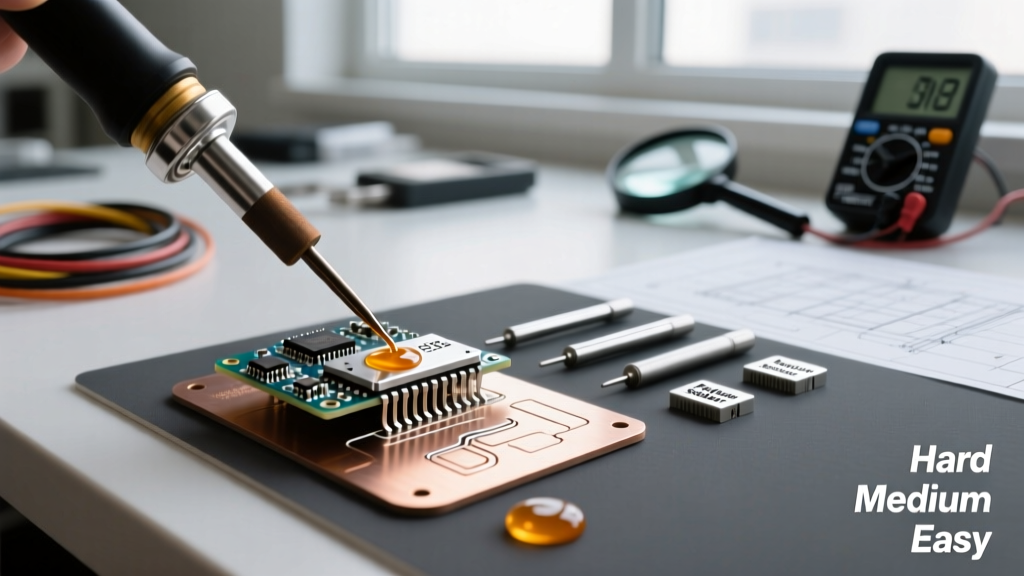
For heavy copper pours (2 oz or 3 oz copper weight), set your station to 360°C - 380°C. The key is not just temperature, but thermal mass. According to the Hakko Soldering Tip Guide, a heavy-duty chisel tip stores more thermal energy than a fine conical tip. A conical tip (like the T18-B) will instantly drop below 217°C upon touching a copper plane, resulting in a cold, grainy joint. Always use the widest tip that the physical geometry of the joint allows.
Q3: Why does my solder joint on copper look dull and grainy instead of shiny?
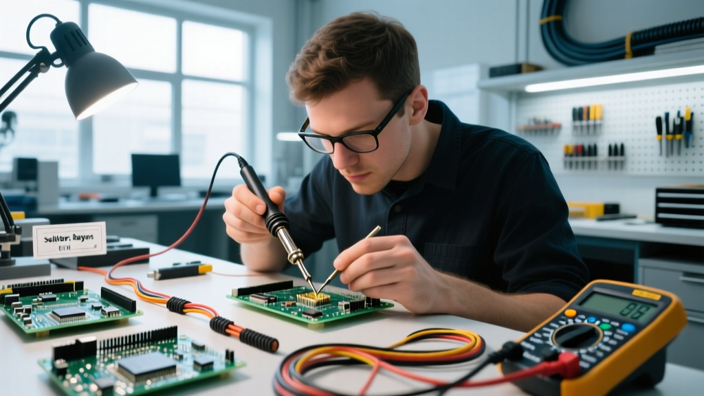
A: A dull, grainy appearance is the hallmark of a disturbed joint or a cold joint. If you are using standard Sn63/Pb37 (which melts at 183°C), the joint must remain completely motionless while it transitions from the liquidus state down through the solidus state. If the copper wire shifts even a fraction of a millimeter during this 1-to-2-second cooling window, the crystalline structure fractures, resulting in a grainy, weak connection. Secure the copper workpiece in a helping-hands fixture or a silicone vise block before applying heat.
Pro Tip for 2026: If you frequently struggle with grainy joints on large copper heat sinks, consider switching to a low-temperature alloy like Sn42/Bi57 (Bismuth-Tin). It melts at just 138°C, virtually eliminating the risk of disturbed joints and thermal damage to FR4 substrates, though it should not be used in high-vibration environments due to bismuth's inherent brittleness.
Emergency Pad Recovery Protocol
If you applied too much heat and a copper pad has lifted off the PCB, the joint is structurally compromised. Do not attempt to simply glue the pad back down; it will fail under mechanical stress. Follow this IPC-compliant recovery method:
- Clean the Area: Use a fiberglass scratch pen to gently remove the solder mask and expose the bare copper trace leading away from the lifted pad.
- Prepare the Jumper: Cut a 1-inch piece of 30 AWG bare copper wire. Tin both ends of the wire with Sn63/Pb37 solder.
- Bridge the Connection: Solder one end of the tinned wire to the exposed, scraped trace. Solder the component lead directly to the other end of the jumper wire, bypassing the ruined pad entirely.
- Secure the Repair: Apply a two-part structural epoxy (such as Loctite EA 9460) or a UV-curable solder mask resin over the jumper wire and the scraped trace. Cure completely to restore mechanical rigidity and prevent the trace from peeling under wire tension.
Final Thoughts on Copper Mastery
Successful copper soldering is less about raw heat and more about thermal management, surface chemistry, and mechanical preparation. By matching your tip geometry to the copper's thermal mass, selecting the correct flux activator for the level of oxidation, and respecting the thermal limits of your PCB substrate, you will consistently produce bright, concave, and structurally flawless joints.