
The Thermodynamics of High-Volume Assembly
In hobbyist electronics, setting a soldering iron to 350°C and touching it to a pad is often sufficient. However, in industrial manufacturing and high-reliability prototyping, the concept of PCB soldering temp is not a single static number. It is a complex, dynamic thermodynamic profile that must account for component thermal mass, solder alloy metallurgy, flux activation chemistry, and the glass transition limits of the laminate substrate. Getting this profile wrong doesn't just result in a weak joint; it leads to catastrophic field failures, latent defects, and scrapped production runs costing thousands of dollars per hour in downtime.
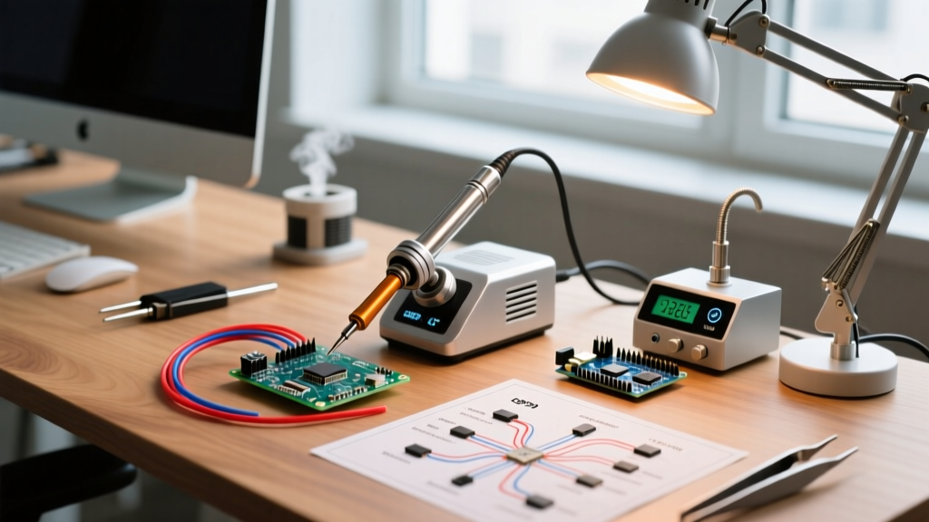
Modern surface mount technology (SMT) and through-hole assembly lines rely on precise thermal management. Whether utilizing convection reflow ovens, selective wave soldering machines, or advanced manual rework stations, understanding the governing parameters of PCB soldering temp is the dividing line between amateur assembly and industrial-grade manufacturing.
IPC J-STD-001 and the Governing Industry Standards
Industrial electronics manufacturing is strictly governed by the IPC (Association Connecting Electronics Industries). Specifically, IPC J-STD-001 (Requirements for Soldered Electrical and Electronic Assemblies) and IPC-A-610 (Acceptability of Electronic Assemblies) dictate the acceptable visual and metallurgical outcomes of solder joints. While these documents focus heavily on the final inspection criteria, they implicitly mandate strict adherence to thermal profiles to prevent defects like cold joints, disturbed joints, and excessive intermetallic compound (IMC) growth.
Industry Insight: Intermetallic compound (IMC) formation is necessary for a valid electrical and mechanical bond. However, excessive time above the liquidus temperature (TAL) causes the IMC layer to grow too thick, resulting in a brittle joint prone to mechanical shock failure. Controlling the PCB soldering temp profile is fundamentally about optimizing IMC thickness, typically targeting 1 to 3 micrometers.
Reflow Soldering Temperature Profiles (SAC305 Lead-Free)
For the vast majority of commercial and industrial SMT assembly in 2026, SAC305 (96.5% Tin, 3.0% Silver, 0.5% Copper) is the baseline lead-free alloy. Its liquidus (melting) point is 217°C. A standard linear reflow profile for SAC305 is broken down into four critical phases. Deviating from these parameters risks either incomplete wetting or thermal damage to the FR-4 substrate and silicon dies.
| Profile Phase | Target Temperature Range | Time / Ramp Rate | Industrial Purpose |
|---|---|---|---|
| 1. Preheat (Ramp) | Room Temp to 150°C | 1.0°C to 3.0°C / sec | Evaporates solder paste solvents; prevents thermal shock to ceramic capacitors. |
| 2. Thermal Soak | 150°C to 200°C | 60 to 120 seconds | Activates flux chemicals to remove oxidation; equalizes temperature across varying component masses. |
| 3. Reflow (Peak) | 235°C to 250°C (Peak) | 45 to 90 sec (Time Above 217°C) | Melts the alloy; promotes capillary action and IMC formation at the pad interface. |
| 4. Cooling | Peak down to 150°C | Max 4.0°C / sec | Prevents grain coarsening and component shifting; avoids warping the PCB substrate. |
Wave Soldering Parameters for Through-Hole Components
While SMT dominates, industrial applications like power supplies, automotive relays, and heavy machinery controllers still rely on through-hole components. Wave soldering introduces a different set of PCB soldering temp challenges, primarily because the board is exposed to a massive thermal shock when contacting the molten solder wave.
- Preheat Zone: The top side of the PCB must reach 90°C to 130°C before hitting the wave. This activates the flux and prevents the board from warping or the solder from freezing upon contact.
- Wave Contact Temperature: The molten SAC305 bath is typically maintained between 255°C and 265°C. This is significantly higher than reflow peak temperatures because the thermal mass of the board and the component leads instantly draw heat away from the wave.
- Dwell Time: The board must remain in contact with the wave for exactly 2.0 to 4.0 seconds. Anything less results in non-wetting and skipped joints; anything more risks dissolving the copper pads (leaching) and damaging component seals.
Manual Rework and High-Reliability Hand Soldering
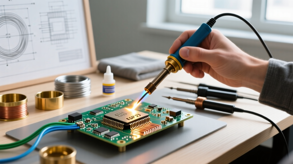
In industrial rework, low-volume aerospace prototyping, and repair, manual soldering is unavoidable. The misconception that a hand soldering iron should be set to the alloy's melting point (e.g., 217°C for SAC305) is a primary cause of cold solder joints in professional environments.
The Thermal Recovery Imperative
When a 350°C iron tip touches a large copper ground plane, the tip temperature can instantly plummet by 100°C or more. If the station cannot recover that heat within a second, the solder will not flow, and the operator will instinctively press harder and hold longer, leading to pad delamination. Therefore, the set PCB soldering temp for hand soldering lead-free alloys is typically 350°C to 380°C.
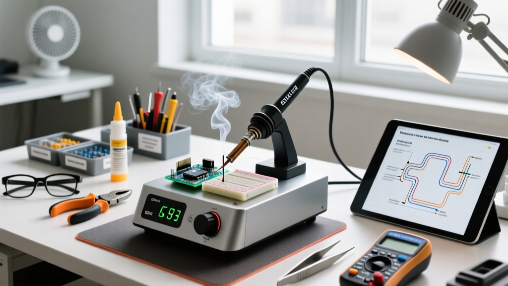
For high-thermal-mass boards, industrial facilities utilize advanced stations like the JBC CD-2BQF (priced around $1,150) or the Hakko FX-951 (priced around $550). These systems feature composite cartridge tips where the heating element is integrated directly into the tip itself, rather than separated by an air gap or ceramic sleeve. This design allows for thermal recovery times of under 2 seconds, ensuring the actual temperature at the solder joint remains stable despite the heat sink effect of the PCB.
Advanced Thermal Profiling in 2026 Production Lines
Setting the oven or iron to a specific temperature does not guarantee the PCB assembly actually experiences that temperature. A board with a dense BGA (Ball Grid Array) processor and large aluminum electrolytic capacitors will have massive thermal gradients. The small 0402 resistors might hit 250°C, while the center of the BGA barely reaches 210°C, resulting in head-in-pillow (HiP) defects.
To solve this, industrial engineers use thermal profiling systems from companies like KIC Thermal or Datapaq. These systems involve attaching 6 to 12 thermocouples directly to critical points on the PCB (using high-temperature Kapton tape and aluminum tape). The profiler travels through the reflow oven alongside the board, logging the exact temperature every 0.1 seconds. This data is used to adjust oven zone setpoints and conveyor speeds, ensuring the entire board achieves the optimal PCB soldering temp without exceeding the maximum temperature ratings of sensitive silicon components.
Critical Failure Modes: The Cost of Incorrect Temperatures
Understanding the exact failure modes associated with thermal deviations is crucial for process engineers and quality assurance teams. Below is a diagnostic matrix for common thermal-induced defects.
| Thermal Deviation | Resulting Defect | Physical Mechanism | Industrial Consequence |
|---|---|---|---|
| Peak Temp Too Low / TAL Too Short | Cold Solder Joint / Non-wetting | Flux fails to fully activate; alloy does not reach proper liquidus to form IMC layer. | High electrical resistance; joint fractures under minor mechanical vibration. |
| Ramp Rate Too Fast | Tombstoning / Solder Splatter | Solvents in the paste boil violently; unequal wetting forces pull components upright. | Open circuits; requires costly manual X-ray inspection and rework. |
| Peak Temp Too High / TAL Too Long | Pad Delamination / Substrate Blistering | Epoxy resin in the FR-4 substrate exceeds its decomposition temperature (Td), releasing gases. | Total board scrap; internal via barrel cracking leading to latent field failures. |
| Cooling Rate Too Slow | Grain Coarsening / Dull Joints | Slow crystallization allows large, weak grain structures to form in the solder matrix. | Reduced fatigue life; joints fail under thermal cycling in automotive/aerospace environments. |
Conclusion: Precision as a Competitive Advantage
In the modern electronics manufacturing landscape, treating the PCB soldering temp as a mere suggestion is a liability. Whether you are programming a 10-zone convection reflow oven for a high-volume consumer product run, or manually reworking a 12-layer telecommunications backplane, strict adherence to thermal profiles is non-negotiable. By leveraging IPC standards, utilizing rapid-recovery soldering equipment, and validating processes with inline thermal profilers, manufacturing facilities can drastically reduce defect rates, ensure long-term product reliability, and maintain the rigorous quality standards demanded by today's market.