
The 2026 Landscape of Through-Hole PCB Soldering
As electronic assemblies evolve toward higher power densities and mixed-technology architectures, the challenge of soldering on PCB substrates with complex through-hole technology (THT) components has never been more critical. While surface mount technology (SMT) dominates via reflow ovens, industries such as automotive EV powertrains, aerospace avionics, and industrial IoT rely heavily on THT for mechanical strength and high-current carrying capacity. In 2026, EMS (Electronics Manufacturing Services) providers must choose between wave, selective, and automated robotic soldering to meet the stringent IPC-A-610 Class 3 acceptability requirements.
This guide provides a deep-dive technical comparison of the primary industrial methods for soldering on PCB assemblies, analyzing capital expenditure (CapEx), cycle times, defect rates, and thermal management strategies.
Wave Soldering: The High-Volume Workhorse
Wave soldering remains the undisputed champion for high-volume, low-mix (HVLM) manufacturing where boards are densely populated with THT components. Modern wave systems, such as the Ersa Powerflow e N2, utilize a dual-wave mechanism: a turbulent 'chip wave' to push solder into tight clearances, followed by a laminar 'lambda wave' to smooth the joints and eliminate bridging.
Technical Specifications & CapEx
- CapEx Range: $90,000 – $150,000 (depending on nitrogen inerting and pallet automation)
- Solder Pot Capacity: 400kg – 500kg (typically SAC305 or SnCuNi alloys)
- Nitrogen Consumption: < 20 m³/h (crucial for reducing dross generation by up to 85%)
- Throughput: 100 – 150 boards per hour
Selective Soldering: Precision for Complex Mixed-Tech
When boards feature a high ratio of SMT to THT components, or when THT parts are located dangerously close to heat-sensitive SMT parts, wave soldering becomes unviable. Selective soldering systems, like the Pillarhouse Orion or Ersa Versaflow 4/55, utilize a drop-jet fluxer and a miniature, programmable solder nozzle to target specific pins.
The Physics of the Miniature Wave
Selective soldering on PCB layouts requires precise thermal management. The localized solder bath creates a 'thermal shadow' effect. If a large ground plane is connected to a THT pin, the heat sinks away from the joint, leading to cold solder defects or insufficient barrel fill. Modern systems counter this with top-side preheat modules utilizing quartz IR or forced convection to bring the board to 110°C–130°C before the nozzle makes contact.
"The shift toward lead-free, high-reliability alloys like SN100C (Sn-Cu-Ni) in selective soldering has necessitated longer dwell times—typically 2.5 to 4.0 seconds per pin—to ensure proper wetting and compliance with IPC-J-STD-001 barrel fill requirements." — Assembly Magazine Process Engineering Report
Automated Robotic Soldering: The Flexible Alternative
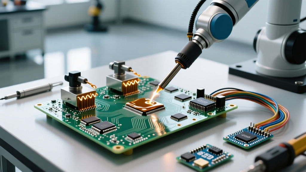
For low-volume, high-mix (LVHM) environments, or for components that cannot withstand the thermal shock of a wave or selective bath (e.g., certain RF connectors, heavy transformers, or optical sensors), automated robotic soldering is the optimal choice. Systems like the JBC RMVE-2A or Quick 938BD integrated cells use vision-guided robotics paired with high-thermal-capacity soldering irons or localized laser heating.
Laser vs. Iron-Based Robotics
- Iron-Based (Contact): Uses cartridge-style tips (e.g., JBC C245 series) with integrated thermocouples. The system reads the thermal demand of the joint and pumps power instantly. CapEx: $35,000 – $60,000.
- Laser Soldering (Non-Contact): Utilizes a 980nm diode laser to heat the pad and pin directly without touching the board. Ideal for ultra-fine pitch or heat-sensitive substrates like flexible PCBs. CapEx: $80,000 – $120,000.
Comparative Matrix: 2026 Industrial Soldering Methods
The following table breaks down the critical metrics for manufacturing engineers evaluating capital equipment for soldering on PCB lines.
| Method | CapEx (USD) | Cycle Time / Board | Best Application | Primary Defect Risk |
|---|---|---|---|---|
| Wave Soldering | $90k - $150k | 15 - 30 seconds | HVLM, 100% THT boards | Bridging, Icicles |
| Selective Soldering | $160k - $250k | 60 - 180 seconds | Mixed-tech, tight clearances | Insufficient barrel fill |
| Robotic (Iron) | $35k - $60k | 3 - 8 mins | LVHM, heat-sensitive THT | Cold joints, flux burn |
| Robotic (Laser) | $80k - $120k | 2 - 5 mins | Flex PCBs, micro-THT | Pad delamination |
Flux Chemistry and Preheat Profiling
Regardless of the mechanical method chosen, the chemical preparation of the board dictates the success of soldering on PCB assemblies. In 2026, VOC-free, water-based fluxes (such as Kester 2331-ZX or Indium Corporation #550) are the industry standard to comply with environmental regulations.
The Preheat Ramp Rate Constraint
A critical failure mode in automated soldering is thermal shock to multi-layer ceramic capacitors (MLCCs). If the preheat ramp rate exceeds 2°C to 3°C per second, micro-cracking can occur in the ceramic dielectric, leading to latent field failures. Manufacturing engineers must program preheat zones to ensure a gentle slope, utilizing bottom-side IR and top-side forced convection to achieve a delta-T of less than 10°C across the board surface before it contacts the solder wave or nozzle.
Defect Mitigation and IPC Compliance
Adhering to industry soldering standards requires active mitigation of common THT defects:
- Insufficient Barrel Fill: IPC-A-610 Class 3 requires a minimum of 75% barrel fill for high-reliability products. This is mitigated in selective soldering by increasing the nozzle dwell time by 0.5s and ensuring the top-side preheat reaches at least 120°C to promote capillary action.
- Solder Bridging: Common in wave soldering on PCB layouts with tight pin spacing (e.g., 1.27mm pitch connectors). Solved by optimizing the board's orientation on the conveyor (angling the board 5° to 7°) and using nitrogen-inerted environments to lower the solder's surface tension.
- Blowholes / Outgassing: Caused by moisture trapped in the PCB laminate or flux solvents boiling inside the plated through-hole (PTH). Baking boards at 125°C for 4 hours prior to soldering is a mandatory step for high-reliability aerospace assemblies.
Strategic Buyer's Framework for 2026
When investing in secondary soldering equipment, EMS providers and OEMs should apply the following decision matrix:
- Choose Wave Soldering if: Your product mix consists of legacy industrial controls, power supplies, or automotive ECUs with high THT density, and your annual volume exceeds 500,000 units.
- Choose Selective Soldering if: You are manufacturing mixed-technology boards where SMT components are placed within 2mm of THT pins, eliminating the possibility of using wave solder pallets.
- Choose Robotic Soldering if: Your facility operates in a High-Mix, Low-Volume (HMLV) environment, or you process boards with extreme thermal mass variations that cause selective soldering nozzles to stall or drop temperature.
Final Thoughts on Automation
The landscape of soldering on PCB assemblies is rapidly consolidating around data-driven process control. Modern selective and wave machines now feature closed-loop feedback systems that monitor nozzle wear, flux specific gravity, and solder pot contamination (like copper leaching) in real-time. Investing in equipment with Industry 4.0 / IPC-CFX connectivity is no longer optional for Tier 1 manufacturers; it is a prerequisite for traceability and yield optimization in 2026 and beyond.