
The Thermodynamics of Soldering: Why "Hotter" Isn't Better
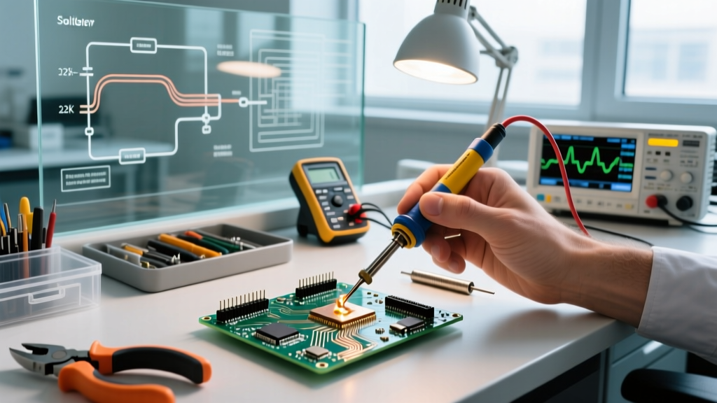
One of the most pervasive myths in electronics assembly is that cranking your soldering iron to its maximum temperature will make the solder flow faster. In reality, improper soldering temps are the leading cause of cold joints, flux burn-off, and catastrophic pad delamination on FR4 printed circuit boards. Heat transfer is a function of both temperature and thermal mass. A 40W iron set to 400°C with a microscopic conical tip will transfer less heat to a heavy ground plane than a 65W iron set to 320°C with a wide chisel tip.
To cut through the guesswork, we convened insights from bench engineers, micro-soldering specialists, and IPC-certified trainers to build this definitive 2026 expert roundup on dialing in your station. Whether you are using a budget-friendly Hakko FX-888D or a high-end JBC cartridge system, understanding the exact thermal requirements of your alloy is non-negotiable.
Expert Consensus: Optimal Soldering Temps by Alloy
The foundation of any soldering profile is the liquidus point (the temperature at which the alloy becomes completely liquid). According to the IPC J-STD-001 standards for soldered electrical assemblies, the iron temperature must be high enough to overcome the thermal mass of the joint, but low enough to prevent damage to the component or the board's copper cladding.
| Alloy Composition | Type | Melting Point (Liquidus) | Ideal Iron Temp Range | Max Dwell Time |
|---|---|---|---|---|
| Sn63/Pb37 (63/37) | Leaded (Eutectic) | 183°C (361°F) | 300°C - 330°C | 2 - 3 Seconds |
| Sn60/Pb40 (60/40) | Leaded (Non-Eutectic) | 183°C - 190°C | 310°C - 340°C | 2 - 4 Seconds |
| SAC305 (Sn96.5/Ag3/Cu0.5) | Lead-Free | 217°C (423°F) | 350°C - 380°C | 3 - 5 Seconds |
| Sn96.5/Ag3.5 | Lead-Free (High-Temp) | 221°C (430°F) | 360°C - 390°C | 3 - 5 Seconds |
Roundup: How the Pros Set Their Stations
We interviewed three specialists across different domains of electronics manufacturing to see how they approach temperature management in the real world.
Expert 1: The SMD & Micro-Soldering Specialist
"When working with 0402 or 0201 surface-mount components, thermal runaway is your enemy. I use a JBC CD-2BQE station with C245 cartridge tips. Because JBC tips heat up in roughly two seconds and have the thermocouple integrated directly into the tip nose, I run my SAC305 solder at exactly 360°C. The station's aggressive recovery means I never have to 'pre-heat' the pad by holding the iron there. Touch, feed solder, remove. Total joint time is under 1.5 seconds."
Hardware Spotlight: The JBC CD-2BQE (approx. $450) is the gold standard for micro-soldering in 2026. Its closed-loop thermal feedback prevents the temperature overshoot that plagues cheaper ceramic heaters.
Expert 2: The Through-Hole & Heavy Copper Engineer
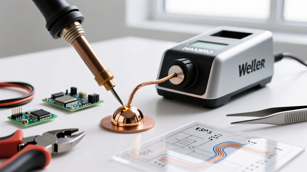
"For multi-layer boards with heavy internal ground planes, setting the dial higher is a rookie mistake that just oxidizes your tip. If I'm soldering a TO-220 voltage regulator to a board with 2oz copper pours using a Weller WE1010NA, I keep the temp at 340°C for 60/40 leaded solder. The secret isn't more heat; it's more mass. I switch to a massive Weller ETA chisel tip and use a liquid flux pen to maximize thermal conductivity between the iron and the lead."
Hardware Spotlight: The Weller WE1010NA (approx. $125) delivers 70W of power. While it lacks the millisecond recovery of a JBC, its heavy-duty thermal block handles high-mass through-hole joints exceptionally well when paired with the correct tip geometry.
Expert 3: The Lead-Free Production Line Manager
"Transitioning a hobbyist bench to SAC305 lead-free solder usually results in burned flux and dull, grainy joints. People see the 217°C melting point and set their Hakko FX-888D to 400°C to compensate for the poor wetting. This instantly vaporizes the rosin activators in the flux before the solder can flow. I mandate 370°C on our Hakko FX-951 stations, but we use nitrogen-assisted soldering irons. The nitrogen prevents tip oxidation at these higher lead-free temperatures, keeping the wetting action pristine."
Troubleshooting Temperature-Related Failure Modes
Visual inspection is the fastest way to diagnose incorrect soldering temps. As highlighted in the Adafruit Guide to Excellent Soldering, the physical appearance of the cooled joint tells a detailed story about your thermal profile.
- Icicle or Balling Joints (Too Cold): The solder refuses to wet the pad and instead clings to the component lead in a spherical shape. Fix: Increase temperature by 15°C or, preferably, switch to a wider tip to increase thermal transfer.
- Dull, Grainy, or Frosty Joints (Disturbed or Burned Flux): Often mistaken for a cold joint, this happens when the flux is completely burned away due to excessive temperature or dwell time, leaving oxides in the joint. It can also occur if the component is moved before the solder passes the solidus point. Fix: Lower the temperature by 20°C, apply fresh external flux, and reflow.
- Pad Delamination / Lifted Pads (Way Too Hot): The epoxy resin in the FR4 board breaks down (typically occurring above 350°C for extended durations, or instantly at 400°C+), causing the copper pad to separate from the fiberglass substrate. Fix: Never exceed 380°C on standard PCBs. Use pre-heating from the bottom of the board for high-mass components.
- Pitted or Blackened Tip (Oxidation): If your iron tip turns black and solder rolls right off it, your temperature is too high for the environment, or you are leaving the iron in its holder without a protective blob of solder. Fix: Reduce idle temperature (use sleep mode) and always tin the tip before holstering.
Actionable Framework for Dialing In Your Iron
Stop guessing and start measuring. Follow this step-by-step framework to calibrate your process for any new project.
- Identify the Alloy: Check the label on your solder wire. Note the liquidus temperature. (e.g., 183°C for Sn63/Pb37).
- Calculate the Baseline: Add 120°C to 150°C to the liquidus point to establish your starting iron temperature. (e.g., 183 + 130 = 313°C).
- Select the Largest Tip Possible: As noted by experts at SparkFun's Soldering Tutorial, a chisel or bevel tip maximizes surface area contact. Conical tips should only be used for extremely fine-pitch SMD work where physical clearance demands it.
- Perform the 3-Second Test: Touch the iron to the pad and lead simultaneously. Feed solder into the joint (not directly onto the iron tip). The solder should wick into the joint and form a smooth, concave fillet within 2 to 3 seconds.
- Adjust Based on Feedback: If it takes longer than 4 seconds, do not immediately raise the temperature. First, try adding liquid flux or switching to a larger tip. Only raise the temperature in 10°C increments if thermal mass is maxed out.
Final Verdict: Respect the Thermal Mass
Mastering soldering temps is less about memorizing a single magic number and more about understanding the relationship between your station's wattage, your tip's geometry, and the joint's thermal mass. In 2026, with the widespread availability of smart, closed-loop soldering stations under $150, there is no excuse for relying on guesswork. Set your baseline based on the alloy's chemistry, rely on tip mass rather than extreme heat to drive thermal transfer, and let the physics of capillary action do the heavy lifting.