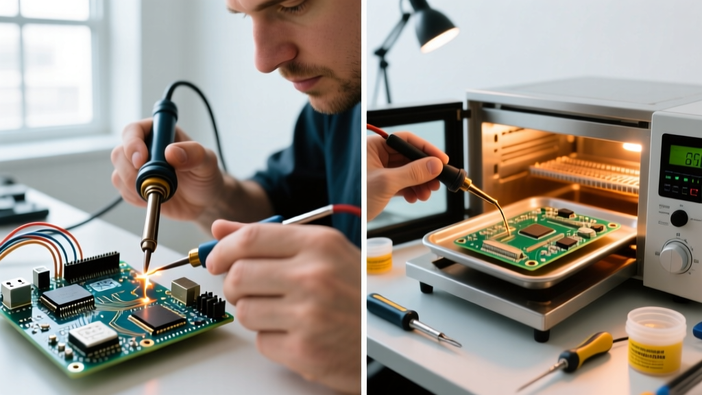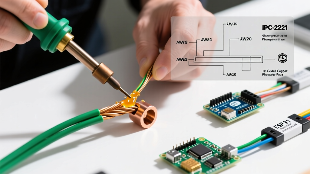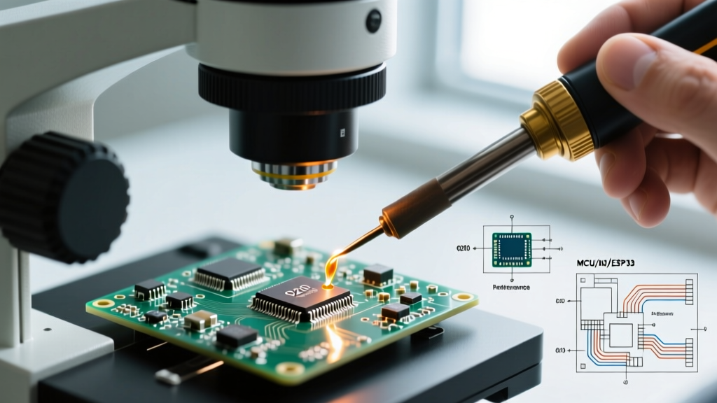

The landscape of electronics repair and DIY fabrication has shifted dramatically. With the 2026 boom in ultra-compact AR glasses, medical IoT wearables, and high-density drone flight controllers, miniature soldering is no longer restricted to aerospace engineers. Hobbyists and board-level repair technicians are now routinely tackling 0201 (0.6mm x 0.3mm) and even 01005 (0.4mm x 0.2mm) surface-mount devices (SMD). However, shrinking component sizes introduce severe thermal and mechanical challenges. A standard 60W iron and a magnifying glass will instantly destroy a micro-pad. This comprehensive FAQ and troubleshooting guide addresses the most critical failure modes in micro-SMD assembly and provides actionable, expert-level solutions.
The 2026 Micro-Soldering Bench Matrix
Before addressing specific defects, you must verify your hardware. Miniature soldering requires rapid thermal recovery and high-resolution optics. Below is the benchmark equipment matrix for professional-grade micro-soldering.
| Equipment Category | 2026 Benchmark Model | Avg. Cost | Micro-Soldering Role & Specification |
|---|---|---|---|
| Active-Tip Station | JBC CD-2BQE with C245 Handle | $485 | Heater is inside the tip. Reaches 340°C in 2 seconds. Essential for 0201 thermal mass management. |
| Micro-Tip Geometry | JBC C245-945 (0.3mm Blade) | $58 | Allows precise drag-soldering on 0.4mm pitch QFNs without bridging adjacent pins. |
| Trinocular Microscope | AmScope SM-4T (7X-45X) | $430 | Provides depth perception and working distance for simultaneous tweezer and iron manipulation. |
| Tacky Flux | Chip Quik SMD291AX (Type 3) | $28 | Viscous rosin-based flux that holds 0402 components in place via surface tension before reflow. |
| Micro-Solder Paste | Senju M705 (Type 4 Powder) | $65 | 20-38 micron powder size prevents solder balling under 0201 and 01005 terminations. |
Frequently Asked Questions (FAQ)
Can I use standard 63/37 rosin-core wire solder for 0201 resistors?
No. Standard wire solder, even at 0.5mm diameter, is too thick and introduces excessive volume, leading to immediate short circuits or tombstoning on micro-pads. For 0201 and smaller components, you must transition to Type 4 or Type 5 solder paste applied via a micro-syringe or precision stencil. If you absolutely must use wire, you need ultra-fine 0.15mm diameter solder wire paired with a high-activity liquid flux (like Amtech NC-559-V2-TF) to ensure the solder flows before the flux boils off. However, paste remains the industry standard for micro-SMD rework.
Why do my micro-IC pins keep bridging during drag soldering?
Bridging on 0.4mm or 0.5mm pitch ICs (like QFP or TQFP packages) is almost always caused by flux exhaustion and incorrect tip geometry. When drag soldering, the flux activates between 150°C and 180°C, lowering the surface tension of the molten SAC305 (lead-free) solder. If you move too slowly, the flux burns off, and the solder clings to the pins rather than the pads. The Fix: Use a micro-hoof or gull-wing tip (e.g., Hakko T12-B2 or JBC C245-770). Apply a generous bead of tacky flux across the pins *before* introducing the solder. Keep the tip moving at a steady pace of roughly 1mm per second, and always finish the drag stroke by pulling the iron away at a 45-degree angle to let surface tension pull the excess solder onto the tip.
What lighting setup is required for inspecting 01005 solder joints?
Standard LED ring lights create harsh glare on residual flux and smooth solder fillets, masking microscopic cracks or dry joints. For true micro-soldering inspection, you need darkfield illumination or dual gooseneck polarized lights positioned at extreme low angles (10-15 degrees). This lighting technique eliminates surface glare and highlights the actual meniscus (the curved edge) of the solder fillet, allowing you to verify proper wetting according to IPC-A-610 assembly standards.
Troubleshooting Common Micro-SMD Defects
Defect 1: Tombstoning (Drawbridging)
Symptom: One side of a 0201 or 0402 capacitor solders perfectly, while the other end stands straight up, resembling a tombstone.
Root Cause: Asymmetric wetting forces. This happens when one pad reaches reflow temperature (217°C for SAC305) before the other. The surface tension of the molten solder on the hotter pad overpowers the mechanical weight of the micro-component, pulling it upright. This is common near large ground planes that act as heat sinks.
Actionable Fix: Never solder a micro-component by heating one pad, placing the part, and then heating the other. Instead, pre-tin both pads with an equal micro-dot of solder paste. Use a hot air rework station (set to 280°C with a 2mm nozzle) or a pre-heater plate (set to 100°C) to bring the entire local area to a uniform temperature simultaneously. The component will self-align due to the liquid solder's surface tension.
Defect 2: Pad Cratering and Delamination
Symptom: The copper pad lifts off the FR4 substrate, taking the solder mask and underlying fiberglass with it, resulting in an open circuit.
Root Cause: Excessive dwell time and thermal shock. Standard cheap irons suffer from poor thermal recovery. When a user touches a cold iron to a micro-pad, the temperature drops. The user then applies pressure and waits 4-5 seconds for the iron to recover, transferring massive amounts of localized heat that exceeds the glass transition temperature (Tg) of the PCB laminate.
Actionable Fix: Limit dwell time to 1.5 seconds maximum. Use an active-tip station (like JBC or Pace ADS200) that senses the thermal load and injects current directly into the tip's heater element. Set your lead-free profile to 340°C. The tip will recover instantly upon contact, melting the solder in under a second without delaminating the pad.
According to the IPC-A-610 standard for electronic assemblies, a micro-SMD solder joint must exhibit a continuous, smooth fillet with a wetting angle of less than 90 degrees, without any evidence of disturbed or cold crystalline structures. Any visible pad lifting is an immediate Class 3 reject.
Defect 3: Electrochemical Migration (Dendrite Growth)
Symptom: The board works initially but fails weeks later with short circuits between micro-pins, especially in high-humidity environments.
Root Cause: Using the wrong flux chemistry. Many hobbyists use cheap, high-halide organic acid (OA) fluxes that are highly corrosive. In 2026 ultra-low-power wearables operating at 1.2V or lower, even microscopic ionic residues can cause dendritic silver/copper growth across 0.2mm gaps.
Actionable Fix: Exclusively use ROL0 (Rosin, Low activity, 0 halides) no-clean flux for micro-pitch components. While 'no-clean' implies you don't have to wash it, best practice for sub-0.5mm pitch BGA and 0201 arrays is to clean it with 99.9% isopropyl alcohol (IPA) and an ultra-soft hake brush to prevent any long-term leakage current.
Step-by-Step Recovery: Repairing a Lifted Micro-Pad
When a 0.3mm pad tears off during a botched rework, the board is not necessarily dead. You can rebuild the micro-circuit using magnet wire and UV-curable solder mask. For a deeper dive into advanced PCB trace repair, the Adafruit SMT Tutorials offer excellent visual baselines.
- Expose the Trace: Using a fiberglass scratch pen or a #11 scalpel, gently scrape away the solder mask along the trace leading to the missing pad. Expose about 1.5mm of bare copper. Tin this exposed copper lightly.
- Lay the Micro-Wire: Cut a 5mm piece of 0.1mm (AWG 38) polyurethane-coated enameled copper wire. The soldering iron's heat will automatically burn through the enamel coating upon contact. Solder one end of the wire to the exposed trace.
- Form the New Pad: Route the wire to the original pad location. Bend the tip of the wire into a microscopic 'U' shape to mimic the original pad's footprint. Tack it down with a micro-drop of SAC305 paste.
- Anchor with UV Mask: Apply a drop of UV-curable solder mask (e.g., Senju or Elecap) over the wire and the exposed trace, leaving only the new 'U' shaped pad exposed. Cure it under a 365nm UV flashlight for 60 seconds. This provides the mechanical strength needed to withstand the physical stress of placing the 0201 component.
- Final Assembly: Apply ROL0 tacky flux, place the component with anti-magnetic titanium tweezers, and reflow using hot air.
Final Thoughts on Micro-Precision
Miniature soldering is an exercise in physics, chemistry, and thermal management. By abandoning outdated through-hole habits, investing in active-tip technology, and strictly controlling your flux chemistry and dwell times, you can reliably rework 0201 and 01005 components on the most densely packed 2026 logic boards. Always verify your joints under darkfield illumination, and remember that in micro-soldering, less solder and less heat almost always yield superior results.