
The Industrial Case for Soldering Crimp Connectors
In heavy industrial automation, aerospace, and marine environments, standard wire terminations frequently fail under extreme thermal cycling and high-frequency vibration. This is where soldering crimp connectors—specifically solder-seal heat shrink sleeves and specialized solder-cup terminals—become mission-critical. Unlike standard mechanical crimps that rely solely on cold-weld friction, soldering crimp connectors integrate a mechanical crimp band with a thermally activated solder ring, providing both strain relief and an IP67/IP69K environmental seal.
However, the term 'soldering crimp connectors' is often misunderstood by junior technicians. A common and catastrophic mistake in industrial wiring is attempting to solder a standard crimp barrel after crimping. As we will explore through the lens of the IPC/WHMA-A-620 standard, introducing solder into a standard crimp barrel creates a severe defect. This guide clarifies the correct application, installation, and procurement of true solder-crimp solutions for 2026 industrial harnesses.
Decoding IPC/WHMA-A-620: When Solder Meets Crimp
To specify soldering crimp connectors correctly, procurement engineers and floor technicians must understand the boundary between acceptable and defective terminations. The IPC/WHMA-A-620 standard serves as the global benchmark for cable and wire harness assemblies.
The 'Solder Wick' Defect in Standard Crimps
Under IPC-A-620 Class 3 (High-Performance Electronic Products) requirements, solder wicking into the wire crimp barrel of a standard terminal is classified as a Defect. When liquid solder wicks into the stranded wire inside the crimp barrel, it transforms a flexible, multi-strand wire into a rigid, single-conductor mass. Under vibration, the stress concentrates exactly at the exit point of the crimp barrel, leading to rapid metal fatigue and wire breakage. Therefore, you should never solder a standard closed-barrel crimp terminal.
Acceptable Solder-Crimp Technologies
True soldering crimp connectors bypass this defect by separating the solder joint from the mechanical strain relief. The two industry-approved methods include:
- Solder-Seal Sleeves (SolderSleeves): Heat-shrink tubing containing a pre-form solder ring in the center and thermoplastic crimp/sealing rings at the ends. The solder bonds the wire to a ground lead or splice, while the crimp rings provide mechanical grip.
- Solder-Cup Terminals: Connectors where the wire is inserted into a hollow cup and soldered, but the connector itself is not crimped to the wire. The crimping action is reserved for the mating housing or a separate strain-relief clamp.
Top Industrial Solder-Crimp Solutions for 2026
When sourcing components for high-reliability harnesses, generic eBay or Amazon assortments are unacceptable. Industrial buyers must specify mil-spec or UL-recognized components. Below is a comparison of the leading soldering crimp connector families currently dominating the market.
| Brand / Series | Connector Type | Solder Melt Temp | Shrink Temp | Mil-Spec / Certs | Est. Bulk Cost (2026) |
|---|---|---|---|---|---|
| TE Connectivity Raychem SO96 | Solder-Seal Splice Sleeve | 165°C (329°F) | 120°C (248°F) | MIL-DTL-23053/8 | $0.85 - $1.10 / ea |
| Molex Perma-Seal Solder Ring | Heat Shrink Ring Terminal | 183°C (361°F) | 130°C (266°F) | UL 486A / CSA | $0.45 - $0.65 / ea |
| Panduit PV18-Solder | Solder-Cup Disconnect | N/A (Manual Solder) | N/A | UL 486A | $0.70 - $0.90 / ea |
Note: Pricing reflects 2026 B2B distributor rates (e.g., Digi-Key, Mouser) for quantities exceeding 1,000 units. Supply chain stabilization post-2024 has normalized lead times for TE Connectivity's Raychem line to under 4 weeks.
Step-by-Step: Installing Solder-Seal Crimp Connectors
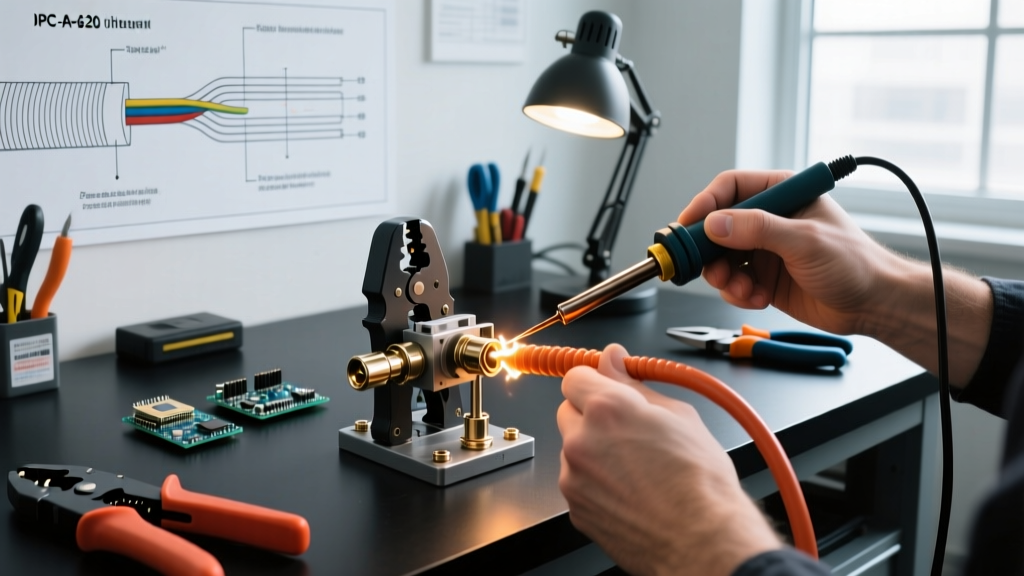
Achieving a Class 3 compliant termination with solder-seal sleeves requires precise thermal management. Using an open flame or an uncalibrated hardware-store heat gun will scorch the polyolefin tubing and oxidize the flux. We recommend using a calibrated industrial hot air tool, such as the Master Appliance MT-5000 (approx. $280), set to the manufacturer's specified airflow and temperature.
Expert Insight: The crimp rings on a solder-seal sleeve are designed to bite into the wire insulation for strain relief. If the wire is not fully seated and held taut during heating, the crimp rings will shrink around empty space, resulting in a failed pull-test.
Installation Protocol
- Preparation: Strip the wire to the exact length specified on the connector datasheet (typically 6mm to 8mm for 18 AWG). Do not tin the wire beforehand; tinning prevents the pre-form solder ring from properly wetting the individual strands.
- Insertion: Slide the solder-seal sleeve over the wire. Insert the stripped conductor into the sleeve until it touches the internal wire stop or aligns with the center solder ring.
- Pre-Heat Phase: Apply moderate heat (approx. 150°C) evenly across the entire length of the sleeve. This activates the heat-shrink polyolefin and secures the crimp rings onto the wire insulation before the solder melts.
- Solder Flow Phase: Concentrate the heat directly on the center solder ring. Watch for the solder to melt and flow outward, creating a visible 'solder fillet' at the edges of the ring. The flux will bubble slightly, cleaning the oxidation.
- Cooling: Remove the heat source immediately. Do not move or flex the wire for at least 15 seconds. Disturbing a cooling solder joint causes a 'cold joint' fracture, characterized by a dull, grainy appearance.
Failure Modes in High-Vibration Environments
Even with premium components like TE Connectivity's Raychem line, field failures occur when installation protocols are violated. According to NASA-STD-8739.4 workmanship standards for crimping and interconnecting cables, the following failure modes are most prevalent in industrial soldering crimp connectors:
- Under-Heating (Cold Solder): The heat shrink activates, but the center solder ring only partially melts. This creates a high-resistance electrical connection that will overheat under load, potentially melting the harness in high-current (10A+) circuits.
- Over-Heating (Insulation Scorch): Excessive heat gun dwell time burns the flux, causing the solder to ball up and refuse to wet the copper strands. The polyolefin outer jacket may also become brittle and crack when subjected to bending.
- Incomplete Crimp Ring Engagement: If the wire gauge is too small for the selected sleeve (e.g., using a 14 AWG sleeve on a 20 AWG wire), the thermoplastic crimp rings at the ends will not compress tightly enough to provide strain relief, failing the IPC pull-test requirements.
Cost Analysis: Solder-Crimp vs. Standard Crimp
Procurement managers often push back on the cost of soldering crimp connectors. A standard vinyl-insulated ring terminal costs roughly $0.12 and takes 4 seconds to crimp using an automated pneumatic crimp press. In contrast, a TE Connectivity solder-seal sleeve costs $0.95 and requires 25 seconds of skilled manual labor with a heat gun.
However, the Total Cost of Ownership (TCO) heavily favors solder-crimp solutions in specific applications. In CNC machinery, robotics, and marine engine bays, a single failed ground wire due to vibration can cause thousands of dollars in downtime or catastrophic ECU damage. The environmental sealing provided by the melted thermoplastic seals prevents moisture ingress and galvanic corrosion, extending the harness lifespan from 3 years to 15+ years. For IP67-rated enclosures and outdoor automation panels, the ROI on solder-seal connectors is undeniable.
Final Recommendations for 2026 Harness Designs
When specifying soldering crimp connectors for your next industrial project, mandate IPC-A-620 Class 3 training for all assembly technicians. Ban the practice of soldering standard crimp barrels, and transition entirely to verified solder-seal sleeves or solder-cup terminals for environments subject to moisture and vibration. By investing in calibrated thermal tools and mil-spec components from established manufacturers like TE Connectivity and Molex, you ensure your wire harnesses meet the rigorous demands of modern industrial automation.
For further reading on advanced wire harness validation, consult the latest TE Connectivity Solder Sleeves engineering guides to match exact wire gauges with their corresponding thermal profiles.