
The Core Question: Is Welding Like Soldering?
When transitioning from structural garage projects to delicate printed circuit board (PCB) repairs, DIYers frequently ask: is welding like soldering? While both are metallurgical joining processes that utilize filler metals and heat to create a bond, the underlying physics, thermal dynamics, and structural outcomes are fundamentally different. To provide a definitive answer, we synthesized insights from AWS Certified Welding Inspectors (CWI), IPC Master Specialists, and metallurgical engineers to break down exactly where these two disciplines converge and where they violently diverge.
"The most dangerous misconception is assuming soldering is just 'low-temperature welding.' In welding, you are altering the crystalline structure of the base metal through fusion. In soldering, you are relying entirely on surface wetting and capillary action without ever compromising the base metal's structural integrity." — Consensus from IPC Master Specialists
The Metallurgical Divide: Fusion vs. Adhesion
To understand the difference, we must look at the state of the base metal during the joining process. According to American Welding Society (AWS) technical resources, welding is defined by the coalescence of materials, typically achieved by melting the workpieces and adding a filler material to form a pool of molten material (the weld pool) that cools to become a strong joint. Soldering, governed by standards like IPC J-STD-001, strictly forbids the melting of the base metal.
| Parameter | MIG/TIG Welding (Steel/Aluminum) | Electronics/Plumbing Soldering |
|---|---|---|
| Base Metal State | Melted (Fused) | Solid (Unchanged) |
| Filler Metal Role | Alloyed into the base metal pool | Adheres to the surface via wetting |
| Typical Temperature | 1,370°C to 3,300°C (2,500°F - 6,000°F) | 183°C to 227°C (361°F - 440°F) |
| Primary Joint Force | Mechanical Penetration & Fusion | Capillary Action & Surface Adhesion |
| Shielding Method | Inert/Active Gases (Argon, CO2) | Chemical Flux (Rosin, Organic Acids) |
Expert Insight 1: Thermal Dynamics & The Heat Affected Zone (HAZ)
Welding inspectors emphasize the critical role of the Heat Affected Zone (HAZ). When you use a Miller Multimatic 220 to lay a MIG bead on 1/4-inch mild steel, the arc temperature exceeds 5,000°F. This intense thermal shock alters the grain structure of the surrounding steel, creating a brittle HAZ that requires post-weld heat treatment (PWHT) in high-stress applications.
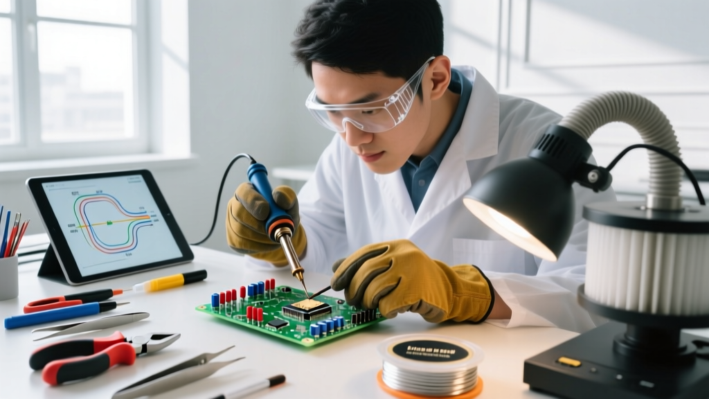
Soldering operates on an entirely different thermal paradigm. When using a precision station like the JBC CD-2BQE (retailing around $480 in 2026), the goal is to transfer just enough heat to overcome the activation temperature of the flux and the liquidus point of the solder alloy—typically 217°C (423°F) for lead-free SAC305. The base copper traces on a PCB remain completely solid. If a DIYer applies too much heat, they don't create a stronger joint; instead, they cause pad lift-off or delaminate the FR-4 fiberglass substrate.
Expert Insight 2: Capillary Action vs. Fusion Penetration
Structural welders are trained to look for "penetration"—the depth to which the weld metal fuses into the root of a joint. A proper TIG weld on a chromoly steel chassis requires a visible "dime" pattern and deep root fusion to withstand torsional loads.
Soldering experts, however, rely on capillary action. When soldering a through-hole component on a protoboard, the molten solder is drawn upward through the plated barrel of the hole by surface tension. The joint's strength is not derived from depth of fusion, but from the total surface area of the intermetallic compound (IMC) layer formed between the copper and the tin. This is why lap joints and tight-fitting mechanical connections are mandatory in soldering, whereas butt joints with V-grooves are standard in welding.
Flux Chemistry vs. Shielding Gas: Protecting the Melt
Both processes face the same enemy: oxidation. When metals reach high temperatures, they rapidly react with oxygen and nitrogen in the atmosphere, creating brittle oxides that ruin joint integrity. The methods used to combat this, however, are vastly different.
Welding: Gas Shielding
In MIG welding, atmospheric contamination is prevented by flooding the arc with a shielding gas. For mild steel, a C25 mix (75% Argon / 25% CO2) is the industry standard. The heavy argon gas displaces the oxygen, while the CO2 stabilizes the arc and increases penetration. If the gas flow rate drops below 15 CFH, or if a draft blows the gas away, the weld will suffer from severe porosity.
Soldering: Chemical Flux
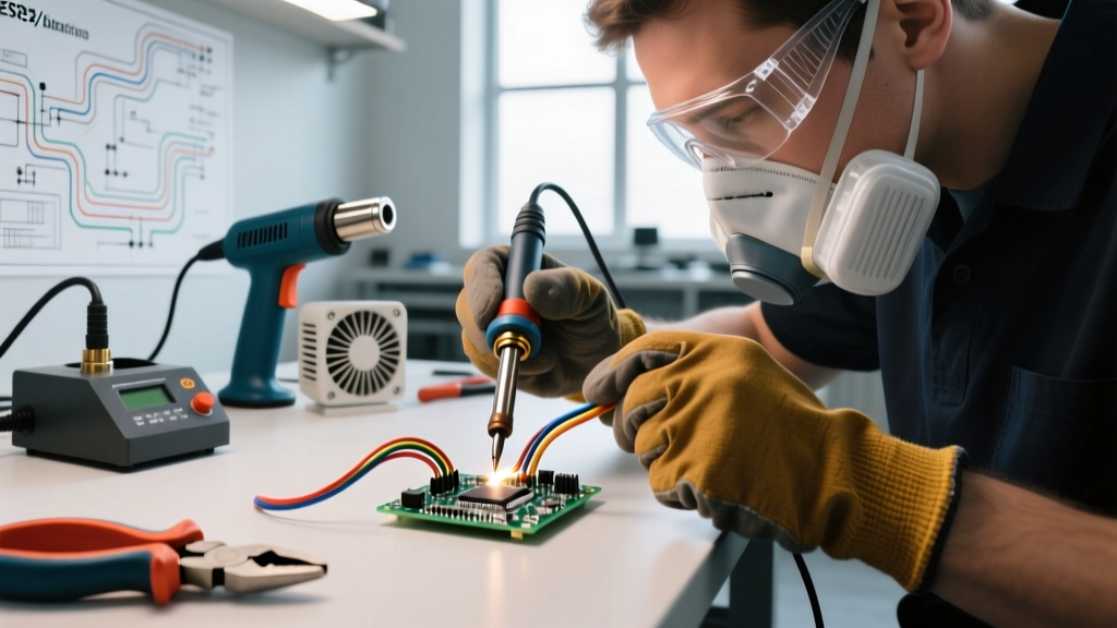
Soldering relies on chemical fluxes rather than gas clouds. In electronics, ROL0 (Rosin, Lightly Activated) flux is standard. When heated, the rosin melts and flows over the copper, physically blocking oxygen. Simultaneously, mild activators (like adipic acid) chemically dissolve existing copper oxide, exposing pristine metal for the molten tin to bond with. Unlike welding gas, flux leaves a solid residue that must be cleaned with isopropyl alcohol (IPA) to prevent long-term dendritic shorting.
Diagnostic Troubleshooting: Comparing Failure Modes
When a joint fails, the diagnostic approach depends entirely on the process. We consulted failure analysis reports to highlight the most common edge cases for both methods.
- Cold Solder Joint (Soldering): Caused by insufficient heat or movement during the cooling phase. The solder cools before the flux can fully clean the surface, resulting in a dull, grainy, and highly resistive connection. Fix: Re-flow with fresh flux and adequate thermal mass.
- Weld Porosity (Welding): Caused by trapped gas (hydrogen, nitrogen, or CO) escaping the freezing weld pool. Appears as tiny pinholes on the surface or internal voids on an X-ray. Fix: Clean base metal of rust/oil, check gas hose for leaks, and reduce travel speed.
- Intermetallic Fracture (Soldering): Occurs when a joint is subjected to prolonged high heat, causing the brittle copper-tin IMC layer to grow too thick. The joint will snap cleanly under mechanical stress. Fix: Use active temperature-controlled tips to minimize dwell time.
- Hydrogen-Induced Cracking (Welding): A catastrophic failure mode in high-carbon steels where moisture from the atmosphere or electrode coating introduces hydrogen into the weld, causing delayed cracking hours after the weld cools. Fix: Bake low-hydrogen electrodes (like E7018) at 250°F for 2 hours before use.
2026 Equipment & Consumables Cost Matrix
For DIYers budgeting their workshop, the barrier to entry and ongoing consumable costs differ drastically between the two disciplines. Below is a snapshot of current market pricing for prosumer-level gear.
| Category | Soldering Setup | Welding Setup (MIG/Flux-Core) |
|---|---|---|
| Primary Power Unit | Hakko FX-888D (~$115) | Hobart Handler 140 (~$650) |
| Filler Material | Kester 245 Sn63Pb37 (~$45/lb) | Blue Demon ER70S-6 (~$35/10lb spool) |
| Consumable Accessories | Hakko T18-B Tips (~$8 each) | 0.030" Contact Tips (~$15/25-pack) |
| Safety Gear | Fume Extractor & Safety Glasses (~$60) | Auto-Darkening Helmet & Leather Jacket (~$180) |
| Total Estimated Entry Cost | ~$228 | ~$880 |
Final Expert Verdict
So, is welding like soldering? The expert consensus is a resounding no. While they share a distant ancestry in the broader field of metallurgical joining, treating them as interchangeable will lead to catastrophic failures. Welding is a brute-force thermal fusion process designed for macro-structural integrity, governed by penetration and shielding gases. Soldering is a micro-precision chemical adhesion process designed for electrical conductivity and delicate mechanical anchoring, governed by capillary action and flux chemistry.
For the modern DIYer, mastering both requires respecting their distinct physical laws. Follow OSHA guidelines for the intense UV radiation and fume hazards of welding, and adhere strictly to IPC wetting standards when designing and repairing electronic assemblies. By understanding the metallurgical divide, you can ensure your structural chassis holds up on the track, and your custom PCB fires up on the first try.