
Introduction to Modern PCB Assembly
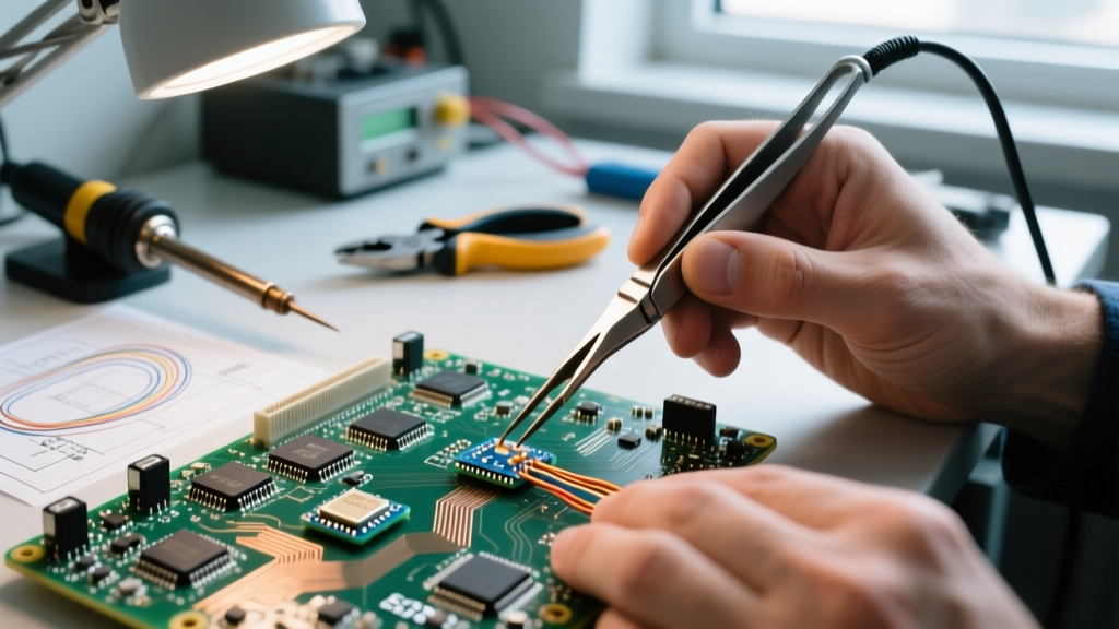
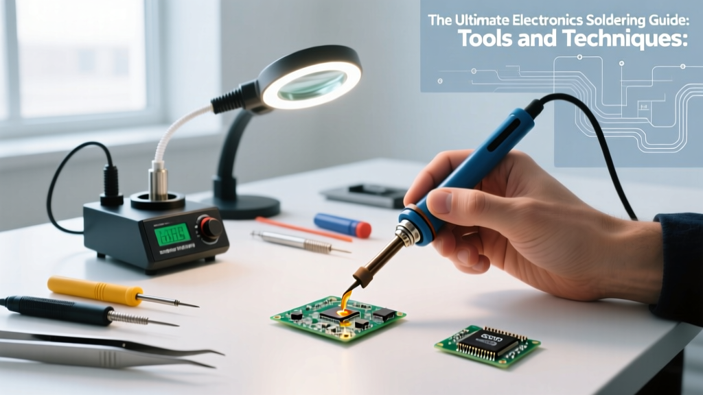
Whether you are assembling a custom mechanical keyboard, repairing a vintage audio amplifier, or prototyping an ESP32-based IoT sensor, mastering the art of soldering is non-negotiable. This comprehensive soldering guide bridges the gap between basic hobbyist tutorials and professional IPC-certified assembly standards. As of 2026, the market has seen a massive shift toward USB-C Power Delivery (PD) smart irons and advanced low-residue no-clean fluxes, making professional-grade results more accessible than ever. In this guide, we will dissect the exact tools, metallurgical principles, and thermal techniques required to produce reliable, inspection-ready solder joints.
Selecting the Right Soldering Station (2026 Market Overview)
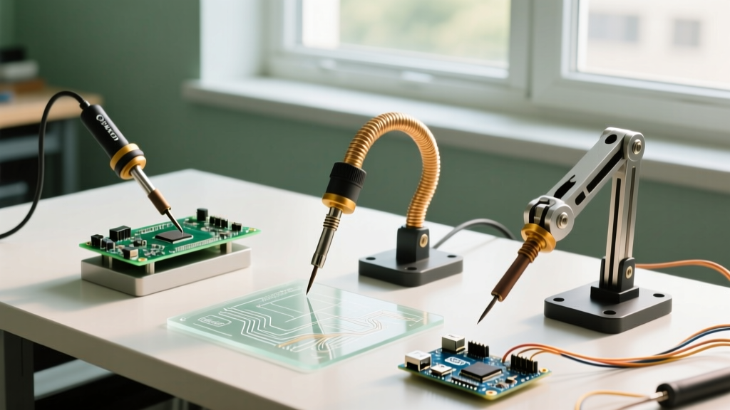
The days of relying on unregulated 40W plug-in irons are over. Modern soldering requires precise thermal recovery to prevent pad liftoff and cold joints. When evaluating a station, prioritize active tip temperature sensing and rapid thermal recovery over raw peak wattage.
Top Tier Stations for Hobbyists and Pros
- Hakko FX-888D ($115 - $130): The undisputed workhorse of the DIY community. It delivers 65W of power and uses the widely available T18 tip series. Its digital interface is straightforward, though the menu navigation remains slightly archaic.
- Weller WE1010NA ($110 - $125): Features a 70W heating element and utilizes the high-performance RT micro-tips. It offers superior thermal stability for heavy ground-plane soldering compared to the Hakko.
- Pine64 Pinecil V2 ($26 - $35): The ultimate portable disruptor. Powered by a RISC-V chip and USB-C PD, it supports up to 65W (with a 20V 3.25A laptop charger) and uses Hakko TS100-compatible tips. Ideal for field repairs and drone technicians.
- JBC CD-2BQE ($550+): The professional benchmark. JBC's proprietary cartridge system integrates the heater directly into the tip, achieving target temperatures in under 2 seconds. Essential for high-volume production or complex multi-layer SMD rework.
| Model | Wattage | Tip Series | Best Application | Est. Price (2026) |
|---|---|---|---|---|
| Pinecil V2 | 65W (via PD) | TS100 / ST | Field repair, Drones, Portability | $30 |
| Hakko FX-888D | 65W | T18 | General through-hole, Basic SMD | $120 |
| Weller WE1010NA | 70W | RT | Precision SMD, Dense PCBs | $115 |
| JBC CD-2BQE | 130W | C245 / C210 | Heavy ground planes, BGA Rework | $580 |
Understanding Solder Alloys and Flux Chemistry
A solder joint is not just melted metal; it is a complex metallurgical and chemical reaction. Choosing the correct alloy and flux is critical for joint reliability and long-term corrosion resistance.
Solder Wire Alloys
For most DIY and prototyping environments in 2026, Leaded 63/37 (Sn63/Pb37) remains the gold standard due to its eutectic properties (melts and freezes at a single temperature of 183°C, eliminating the plastic phase that causes disturbed joints). However, for commercial or RoHS-compliant projects, SAC305 (96.5% Sn, 3.0% Ag, 0.5% Cu) is the industry standard lead-free alloy, requiring higher iron temperatures (320°C - 350°C).
Flux Chemistry: The Unsung Hero
Flux removes oxidation from the copper pads and component leads, allowing the molten solder to 'wet' the surface. According to the IPC J-STD-001 standard, fluxes are categorized by activity and halide content.
- ROL0 (Rosin, Low Activity, 0% Halides): The standard for 'No-Clean' processes. Leaves a benign, non-conductive residue. Recommended: Kester 245 No-Clean.
- ROL1 (Rosin, Low Activity, 1-2% Halides): Offers better wetting on slightly oxidized boards but requires cleaning with isopropyl alcohol (IPA) to prevent long-term dendritic growth.
- Tacky Flux (Syringe): Essential for SMD drag soldering and rework. Recommended: Amtech NC-559-V2-TF.
Pro Tip: Never use plumbing acid flux (zinc chloride) on electronics. It is highly corrosive and will destroy your PCB traces and component leads within weeks. Always stick to electronics-grade rosin or synthetic no-clean fluxes.
The Physics of Wetting: Step-by-Step Technique
Wetting is the process where molten solder displaces flux and forms an intermetallic compound (IMC) layer with the copper pad. A proper IMC layer is typically 1 to 3 microns thick. If the iron is too cool, the IMC doesn't form; if the dwell time is too long, the IMC grows too thick and becomes brittle.
The 5-Step Soldering Sequence
- Clean the Tip: Wipe the iron tip on a damp brass sponge. Never use a wet cellulose sponge, as the thermal shock degrades the tip's iron plating.
- Pre-Tin the Tip: Apply a tiny amount of fresh solder to the tip. This creates a thermal bridge, vastly improving heat transfer to the joint.
- Heat the Workpiece: Touch the pre-tinned tip to BOTH the component lead and the PCB pad simultaneously. Dwell for 1 to 2 seconds.
- Feed the Solder: Apply the solder wire to the joint, not the iron tip. The heat from the workpiece should melt the wire. Feed until a smooth, concave fillet forms (typically 1-2 seconds).
- Withdraw and Cool: Remove the solder wire first, then the iron. Allow the joint to cool naturally. Never blow on the joint, as this causes a 'disturbed joint' with a grainy, fractured appearance.
Tip Geometry: Why Chisel Beats Conical
Many beginner kits include a fine conical (pencil) tip. Discard it immediately. Conical tips have a microscopic surface area touching the flat PCB pad, resulting in terrible thermal transfer. Instead, use a chisel tip (e.g., 2.4mm or 3.2mm). The flat face of a chisel tip maximizes cross-sectional contact with the pad and lead, transferring heat up to 400% faster and reducing the risk of thermal pad damage.
Troubleshooting Common Soldering Defects
Even experienced technicians encounter defects. Referencing the Adafruit Guide to Excellent Soldering and standard IPC visual inspection criteria, here is how to diagnose and fix the most common issues.
- Cold Joint: Appears dull, lumpy, and convex. Cause: Insufficient heat reaching the pad, or moving the joint before it solidified. Fix: Apply fresh no-clean flux, reheat the joint with a clean, pre-tinned tip until the solder flows smoothly, and let it cool undisturbed.
- Solder Bridging (Shorts): Solder connects two adjacent SMD pins. Cause: Too much solder wire or insufficient flux. Fix: Apply generous liquid or tacky flux. Use a clean chisel tip to 'drag' the excess solder away, or use copper desoldering braid (wicking tape) to absorb the excess.
- Tombstoning: One end of a small SMD capacitor lifts off the pad. Cause: Uneven heating of the two pads, causing surface tension to pull the component upright. Fix: Ensure both pads are heated evenly before solder flows. For rework, apply flux to both pads and reflow simultaneously with a hot air gun set to 300°C.
- Pad Liftoff: The copper pad detaches from the fiberglass substrate. Cause: Excessive dwell time (over 4-5 seconds) or excessive downward pressure with the iron. Fix: Prevention is key. If a pad lifts, you must scrape the solder mask off the connected trace and install a wire jumper.
Essential Safety and Fume Extraction
Soldering fumes are primarily composed of vaporized flux (rosin or synthetic activators), not lead vapor (lead does not vaporize at standard soldering temperatures). However, inhaling rosin fumes is a known respiratory sensitizer and can trigger occupational asthma. As highlighted in SparkFun's soldering safety tutorials, proper ventilation is mandatory.
Invest in a dedicated fume extractor with a HEPA and activated carbon filter. The Hakko FA-400 ($65) is a great desktop entry-level option, while the BOFA 3D Print Pro 2 ($1,200+) is the standard for professional labs. At a minimum, use a small desk fan to blow the fume plume away from your breathing zone, directing it toward an open window.
Conclusion
Mastering electronics assembly is a blend of metallurgical understanding and muscle memory. By investing in a temperature-controlled station like the Weller WE1010NA or Pinecil V2, selecting the correct ROL0 no-clean flux, and strictly adhering to proper chisel-tip wetting techniques, you will produce joints that rival automated SMT assembly lines. Keep your tips tinned, respect the thermal limits of your PCBs, and always let the flux do the heavy lifting.