
The Complexity of Modern IC Soldering
As surface-mount technology (SMT) continues to shrink, the art of IC soldering has evolved from a simple hobbyist skill into a precise thermal science. Whether you are repairing a vintage audio amplifier with SOIC-8 chips or prototyping a custom PCB featuring 0.4mm-pitch QFP microcontrollers, selecting the correct soldering methodology is critical. A mismatched technique leads to catastrophic failure modes like thermal pad voiding, tombstoning, or silicon die cracking.
In this comprehensive guide, we compare the three primary methods for IC soldering: the traditional soldering iron (drag and tack), hot air rework, and solder paste reflow. By analyzing thermal profiles, tool costs, and package compatibility, we will help you build the optimal 2026 workbench for integrated circuit assembly.
Method 1: The Soldering Iron (Precision and Drag Soldering)
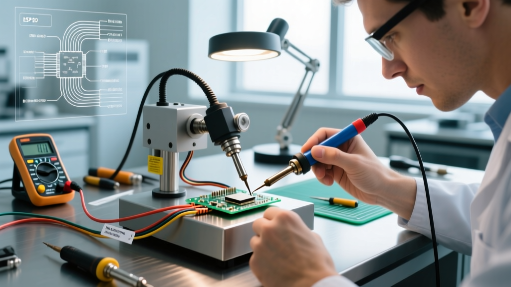
Despite the rise of automated assembly, the manual soldering iron remains indispensable for prototyping, rework, and through-hole/SMD mixed environments. Modern digitally controlled stations, such as the Hakko FX-951 (approx. $330) or the Weller WE1010 (approx. $115), offer rapid thermal recovery essential for maintaining consistent wetting on high-pin-count ICs.
The Drag Soldering Technique
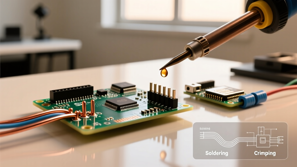
For ICs with exposed peripheral leads—such as SOP, SOIC, and TQFP packages—drag soldering is the most efficient manual method. The process involves applying a generous layer of ROL0 (no-clean) or ROL1 (rosin-based) liquid flux to the pads, tacking two opposite corner pins to align the chip, and then dragging a solder-loaded tip across the entire row of pins.
- Tip Selection: Counterintuitively, a micro-pencil tip is poor for drag soldering. A chisel tip (e.g., Hakko T18-D24) or a specialized drag-soldering tip with a small concave well holds the solder bead via surface tension, allowing it to flow evenly across 0.5mm pitch leads.
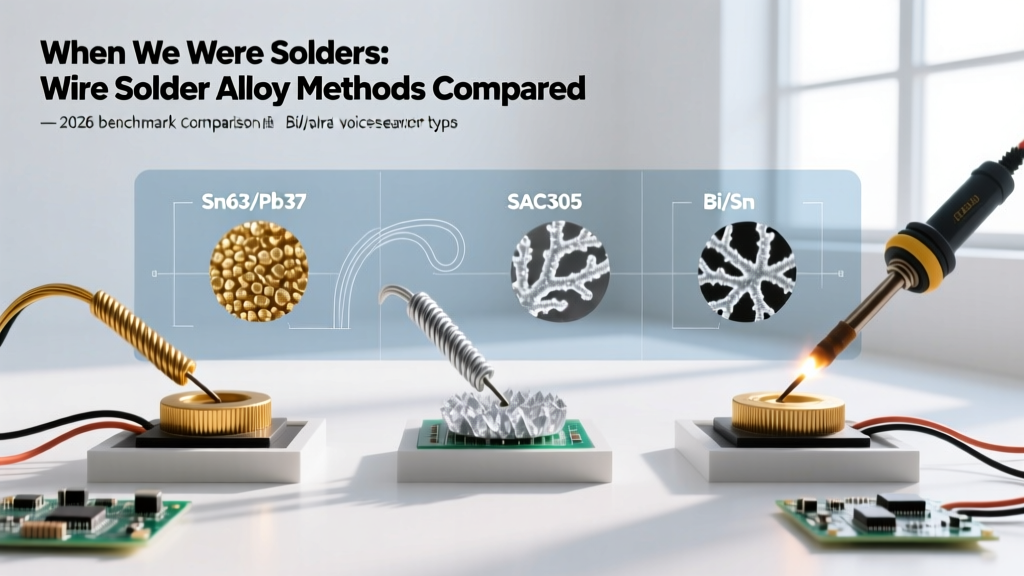
- Temperature Profile: For standard Sn63/Pb37 (leaded) solder, set the iron to 320°C. For SAC305 (lead-free), increase to 360°C to ensure adequate flow without lingering on the pads, which risks delaminating the PCB substrate.
Expert Insight: Always use desoldering braid (e.g., Goot Wick or Chemtronics 2.0mm) to remove bridges after drag soldering. Attempting to 'wipe' away bridges with a dry tip will oxidize the iron and damage the IC's epoxy casing.
Method 2: Hot Air Rework Stations
When dealing with packages that hide their connections underneath the chip—such as QFN (Quad Flat No-leads), DFN, and BGA (Ball Grid Array)—a soldering iron is physically incapable of reaching the pads. Here, convective heating via a hot air rework station is mandatory.
The Quick 861DW (approx. $275 in 2026) remains the gold standard for serious DIYers and repair technicians due to its programmable thermal profiles and high-volume brushless fan. Unlike cheaper stations that rely on high heat to compensate for weak airflow, the 861DW utilizes high airflow (up to 120 L/min) at moderate temperatures, preventing localized scorching.
Mastering the Thermal Profile
IC soldering with hot air requires understanding the thermal mass of the entire PCB. Blasting 400°C air directly onto a QFN-32 chip will melt the plastic housing before the solder on the ground pad liquefies.
- Preheating: Use a bottom-side preheater (or a secondary wide-nozzle hot air gun) to bring the entire board to 120°C–150°C. This reduces the thermal shock and prevents board warpage.
- Top Heat Application: Switch to a nozzle slightly larger than the IC footprint. Apply 350°C–380°C air in a continuous circular motion. The solder is designed to melt via conductive heat transfer from the leads into the chip, not just direct air contact.
- Flux Dependency: Tacky flux (e.g., Amtech NC-559-V2-TF) is mandatory for QFNs. It holds the chip in place via surface tension while the solder reflows, ensuring the hidden thermal pad aligns perfectly with the PCB vias.
Method 3: Solder Paste and Reflow (Hotplate/Oven)
For ultra-fine pitch components (0.4mm and below) or high-volume batch prototyping, manual tools introduce too much human error. Solder paste combined with a reflow hotplate or oven mimics professional SMT assembly lines.
In 2026, the accessibility of laser-cut stainless steel stencils and compact smart hotplates like the Miniware MHP30 (approx. $65) has brought reflow soldering into the home lab. The process involves applying solder paste through a stencil, placing components with tweezers, and heating the board until the paste crosses its liquidus threshold.
Paste Selection and Stencil Geometry
According to industry IPC standards, solder paste is categorized by particle size. For standard 0.5mm pitch ICs, Type 4 paste (20-38 microns) is ideal. For 0.4mm pitch micro-BGAs or QFPs, you must upgrade to Type 5 or Type 6 to prevent solder balling and bridging. Furthermore, stencil thickness must be matched to the pitch: a 4-mil (0.1mm) stencil works for 0.5mm pitch, but a 3-mil (0.075mm) stencil is required for 0.4mm pitch to control paste volume.
Head-to-Head Comparison Matrix
| Feature | Soldering Iron (Drag) | Hot Air Rework | Paste + Reflow Hotplate |
|---|---|---|---|
| Best For | SOIC, SOP, TQFP (Peripheral leads) | QFN, BGA, DFN (Hidden pads) | 0.4mm Pitch, High-Volume, BGA |
| Equipment Cost | $115 - $350 | $180 - $400 | $65 (Hotplate) + Stencil Costs |
| Learning Curve | Moderate (Requires steady hand) | High (Thermal mass management) | Low (Process-driven) |
| Speed per Board | Slow (15-30 mins for complex boards) | Moderate (5-10 mins per IC) | Fast (Batch processing) |
| Reworkability | Excellent (Easy to fix bridges) | Good (Requires wick/cleanup) | Poor (Whole board must be reheated) |
Package-Specific Decision Framework
When planning your assembly or repair workflow, consult this quick-reference framework based on the IC footprint:
- SOIC-8 / SOIC-16: Use a soldering iron. The 1.27mm pitch is massive by modern standards and easily handled with a standard chisel tip and 0.8mm wire solder.
- TQFP-48 / TQFP-100 (0.5mm pitch): Use drag soldering with a high-quality chisel tip and abundant liquid flux, or solder paste if you have a precision stencil.
- QFN-32 / QFN-48: Use hot air. The hidden thermal pad requires convective heat to ensure a solid ground connection and adequate heat dissipation from the silicon die.
- BGA (Ball Grid Array): Use solder paste and reflow (or highly specialized hot air with preheating). Manual inspection of BGA joints requires X-ray equipment, making the repeatable process of reflow paste the only viable option. For deeper insights into high-reliability BGA assembly, refer to the NASA Electronic Parts and Packaging (NEPP) Program workmanship guidelines.
Critical Failure Modes and Edge Cases
Even with the right tools, IC soldering presents unique physical challenges. Understanding these failure modes separates amateurs from professionals.
1. Tombstoning (The Drawbridge Effect)
Tombstoning occurs when a passive component or small IC stands up on one end during reflow. This is caused by uneven heating across the component, resulting in one pad's solder melting and exerting surface tension before the other pad liquefies. Solution: Ensure your hot air nozzle covers the entire component evenly, or use a reflow hotplate which heats the PCB uniformly from below.
2. Thermal Pad Voids in QFNs
QFN packages rely on a large central pad for heat transfer. If air or flux gases become trapped under this pad during hot air soldering, it creates a 'void.' Voids exceeding 25% of the pad area can lead to silicon overheating and premature IC death. Solution: Use a paste with a low-voiding flux chemistry, or design a windowed thermal via pattern on your PCB to allow outgassing, a technique heavily documented in advanced SMD soldering tutorials.
3. Popcorning and Die Cracking
Applying 400°C hot air directly to a moisture-absorbed IC causes the trapped water to rapidly expand into steam, cracking the epoxy casing (popcorning). Solution: Always bake moisture-sensitive ICs (MSL 3 or higher) at 60°C for 12-24 hours before subjecting them to hot air reflow.
Expert Verdict: Equipping Your 2026 Workbench
There is no single 'best' method for IC soldering; the optimal approach is dictated entirely by the silicon package and your production volume. For general-purpose repair, prototyping with leaded SOICs, and fixing minor bridges, a high-quality soldering iron with drag-soldering capabilities is your most versatile tool. However, as modern microcontrollers increasingly adopt QFN and BGA footprints to save board space, integrating a hot air rework station and a reflow hotplate into your lab is no longer optional—it is a strict requirement for modern electronics engineering.