
The Role of the Soldering Jumper in High-Reliability PCB Rework
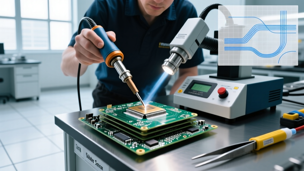
In industrial electronics manufacturing, aerospace, and automotive sectors, a damaged printed circuit board (PCB) trace rarely warrants scrapping the entire assembly. Instead, engineers rely on a soldering jumper to restore electrical continuity. Unlike the colorful Dupont jumper wires used for breadboard prototyping, an industrial soldering jumper refers to specialized micro-wires, polyimide-coated copper strands, or zero-ohm surface-mount components used to bridge broken traces, bypass damaged vias, or modify circuit pathways on high-density interconnect (HDI) boards.
As we navigate the 2026 landscape of miniaturized electronics, the tolerance for error in trace repair is virtually zero. A poorly executed jumper can lead to catastrophic thermal failures, signal integrity loss, or intermittent opens under mechanical vibration. This guide breaks down the material science, industry standards, and purchasing considerations for sourcing and applying soldering jumpers in demanding environments.
Types of Soldering Jumpers for Industrial Applications
Selecting the correct jumper medium is the first critical decision in the rework process. The choice depends on the operating environment, current carrying capacity, and the physical constraints of the PCB layout.
| Jumper Type | Best Application | Max Temp Rating | Approx. Cost (2026) | Pros & Cons |
|---|---|---|---|---|
| Polyimide-Coated Copper Wire | Aerospace, Medical, HDI Boards | 240°C Continuous | $65 - $85 / 100ft spool | Pros: Ultra-thin insulation, high temp resistance. Cons: Requires precise stripping or thermal burn-off. |
| Bare Tinned Copper Wire | Power traces, heavy current bypass | 150°C Continuous | $15 - $25 / 100ft spool | Pros: Excellent solderability, high current capacity. Cons: Risk of short circuits if not properly encapsulated. |
| SMD Zero-Ohm Resistor | Automated SMT line modifications, signal routing | 155°C (Component body) | $0.01 - $0.05 / unit | Pros: Pick-and-place compatible, standardized footprint. Cons: Limited to standard pad spacings, parasitic inductance. |
Navigating IPC and NASA Standards for Trace Repair
In regulated industries, you cannot simply solder a wire across a gap and call it a day. The Association Connecting Electronics Industries (IPC) outlines strict protocols in the IPC-7711/21C standard for the rework, modification, and repair of electronic assemblies. According to these guidelines, a soldering jumper must be secured to the board substrate to prevent mechanical stress from transferring to the solder joint.
Furthermore, the NASA Electronic Parts and Packaging (NEPP) program mandates that jumper wires in spaceflight hardware must withstand extreme thermal cycling (-55°C to 125°C) without inducing solder joint fatigue. This requires the use of specific encapsulants and stress-relief loops. Ignoring these standards in industrial applications can lead to failed compliance audits and voided warranties.
Industry Insight: Never route a soldering jumper directly over a via or a test point unless absolutely necessary. If a crossover is unavoidable, IPC standards dictate the use of a high-dielectric strength Kapton tape layer or UV-curable insulating epoxy between the jumper and the underlying copper.
Selecting the Right Wire Gauge and Solder Alloy
The physical dimensions of your soldering jumper must match the original trace geometry to maintain consistent impedance and current capacity.
Wire Gauge (AWG) Guidelines
- 30 AWG to 34 AWG: Ideal for fine-pitch SMD pads, 0402 components, and low-current signal traces. Often uses polyimide or urethane coating.
- 24 AWG to 28 AWG: Standard for general-purpose logic traces, DIP IC repairs, and moderate current routing.
- 18 AWG to 22 AWG: Reserved exclusively for power rails, ground planes, and high-current bypasses. Requires heavy-duty tinned copper.
Solder Alloy Selection
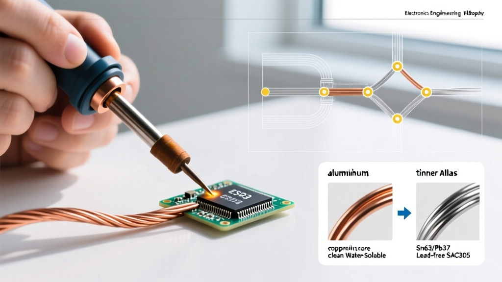
In 2026, the industry remains split between leaded and lead-free alloys depending on the sector. For high-reliability aerospace and medical repairs, Sn63/Pb37 (eutectic) is still heavily favored due to its resistance to tin whisker growth and superior thermal fatigue performance. For commercial and consumer electronics, SAC305 (Sn96.5/Ag3.0/Cu0.5) is the standard. When soldering a jumper with SAC305, ensure your iron tip is set between 340°C and 360°C, as the liquidus temperature is 217°C. Always use a high-activity no-clean flux (such as Amtech NC-559) to ensure proper wetting on oxidized pads.
Step-by-Step: Installing a Soldering Jumper on a Multilayer Board
Follow this precise methodology to ensure a Class 3 compliant repair.
- Trace Preparation: Use a fiberglass scratch pen to gently remove the solder mask and oxidation from the landing pads. Clean with 99% isopropyl alcohol (IPA).
- Pad Tinning: Apply a micro-drop of tacky flux and tin the landing pads with a fine conical tip (e.g., Weller RT3) at 320°C. Keep the iron on the pad for no more than 2 seconds to prevent delamination.
- Jumper Preparation: Cut the polyimide-coated wire to length. Strip the ends using a thermal wire stripper or a scalpel, exposing exactly 1.5mm of copper. Pre-tin the exposed ends.
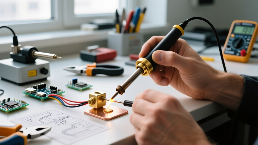
- Placement and Tacking: Position the soldering jumper over the broken trace. Use high-temperature Kapton tape to hold it in place. Tack one end with a minimal amount of solder.
- Final Soldering: Remove the tape, apply fresh flux, and solder the second end. Ensure the solder fillet exhibits a smooth, concave shape with a shiny finish (for leaded) or a slightly dull, grainy finish (for SAC305).
- Encapsulation: Apply a UV-curable structural adhesive (like Loctite 3108) over the jumper and the solder joints. Cure under a 365nm UV LED lamp for 45 seconds to lock the wire in place and provide environmental protection.
Common Failure Modes in Jumper Soldering
Even experienced technicians encounter issues when working with micro-jumpers. Understanding these failure modes is critical for quality control.
- Trace Lifting (Delamination): Caused by excessive dwell time with the soldering iron. The FR-4 substrate softens, and the copper pad peels away. Solution: Use a localized bottom preheater (e.g., Hakko FR-830) set to 120°C to reduce the thermal delta required from the top-side iron.
- Cold Joints: Occurs when the polyimide insulation is not fully cleared from the wire tip before tinning, preventing metallurgical bonding. Solution: Inspect the tinned wire tip under a 20x stereo microscope before placement.
- Parasitic Inductance: A long, looping soldering jumper on a high-frequency RF trace will act as an antenna, destroying signal integrity. Solution: Keep jumpers as short and flat as possible, or use controlled-impedance micro-coaxial jumper wires for RF applications.
2026 Buyer Recommendations: Top Trace Repair Kits
For facilities looking to standardize their rework stations, investing in a comprehensive trace repair kit is more cost-effective than sourcing materials individually.
1. CircuitMedic Trace Repair Kit (CM-TK-01)
Priced around $380 - $420, this is the gold standard for industrial repair labs. It includes a curated selection of polyimide-coated wires (28 to 32 AWG), specialized micro-scrapers, UV epoxy, and a high-intensity LED curing wand. The inclusion of their proprietary fiberglass burnishing pens makes pad prep significantly safer than using standard scalpels.
2. BEST Inc. EZ-Prep and Jumper Station
Coming in at approximately $295, this kit focuses heavily on the chemical and prep side of the repair. It features superior flux gels and precision wire strippers designed specifically for magnet wire and polyimide coatings. It is highly recommended for automotive ECU repair shops where high-volume, thick-gauge jumpering is common.
3. Hakko FR-830 Preheater (Essential Add-on)
While not a jumper kit itself, no industrial jumper station is complete without a preheater. At $1,100, the FR-830 provides uniform bottom heating, drastically reducing the risk of pad lifting when soldering heavy-gauge jumpers to large ground planes. The Surface Mount Technology Association (SMTA) frequently cites uniform thermal profiling as the key differentiator between amateur and professional rework yields.
Ultimately, the success of a soldering jumper repair hinges on material selection, strict adherence to thermal limits, and proper mechanical encapsulation. By investing in aerospace-grade polyimide wires, precision UV encapsulants, and adhering to IPC-7711/21C methodologies, your facility can achieve permanent, high-reliability trace repairs that withstand the rigors of modern industrial deployment.