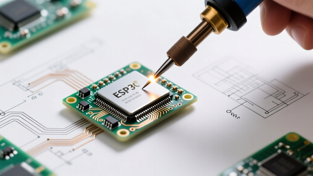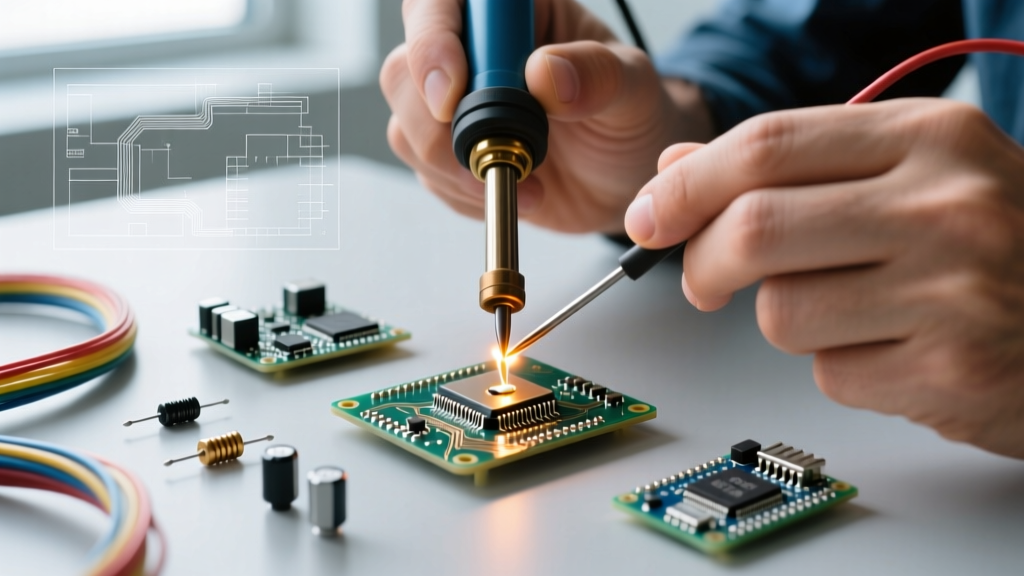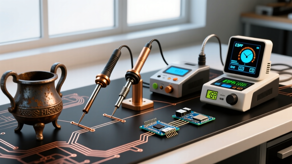

The term solderer historically referred to the artisan wielding the torch, but in modern electronics parlance, it defines the precision thermal delivery system sitting on your workbench. To understand how to buy the right equipment today, one must look at the metallurgical and electronic milestones that forced soldering tools to evolve. From rudimentary copper bits heated in open flames to AI-assisted, RISC-V powered smart stations of 2026, the journey of the solderer is a masterclass in applied physics and materials science.
The Pre-Electric Era: Braziers and 'Coppers'
Before the widespread adoption of electricity, the solderer’s primary tool was simply called a 'copper.' This was a forged copper wedge attached to an iron shank and a wooden handle. According to Encyclopedia Britannica's historical overview of soldering, early artisans heated these coppers in charcoal-fired braziers until they reached the necessary temperature to melt tin-lead alloys.
The primary failure mode of this era was thermal guessing. If the copper was too cool, the solder would 'cold joint' and fail to wet the substrate. If it was too hot, the tin would oxidize instantly, forming a useless dross layer, and the rosin flux would carbonize, destroying its cleaning properties. Solderers had to constantly rotate multiple coppers between the brazier and the workpiece to maintain a narrow thermal window, a highly inefficient process that limited the complexity of early electrical telegraph and radio assemblies.
The Electric Spark and the Transformer Gun
The transition to the electric solderer began in the early 20th century with resistive heating elements wrapped around the copper bit. However, these early plug-in irons suffered from a lack of regulation; they heated continuously until unplugged, often overheating and destroying the iron plating on the tip.
A massive leap occurred in 1941 when Carl E. Weller invented the transformer-based soldering gun. By utilizing a heavy step-down transformer, the gun could deliver massive current (hundreds of amps) at a very low voltage directly through a thick copper wire loop. This allowed the solderer to heat up in seconds and cool down instantly upon releasing the trigger. While transformer guns were revolutionary for heavy chassis wiring and stained glass work, their magnetic fields and bulky tips made them entirely unsuitable for the delicate printed circuit board (PCB) work that would define the latter half of the century.
The Curie Point Revolution: Birth of Closed-Loop Control
As the aerospace and telecommunications industries demanded higher reliability in the 1960s, the unregulated electric iron became a liability. The breakthrough came with the application of the Curie temperature principle. Weller’s Magnastat series utilized a ferromagnetic core inside the tip that lost its magnetic properties once it reached a specific, engineered temperature (the Curie point).
When the tip cooled below this threshold, magnetism returned, pulling a reed switch closed and re-engaging the heating element. This was the first true closed-loop temperature control in a solderer. It meant a technician could swap physical tips to change the maximum temperature limit, ensuring that delicate components were never subjected to thermal runaway. This era also saw the introduction of iron-clad tips, where a copper core was electroplated with iron to resist the corrosive, solvent-like action of molten tin, drastically extending tip life.
The RoHS Shockwave: How Lead-Free Forced a Hardware Redesign
The most disruptive event in the modern history of the solderer was not a technological invention, but a legislative one. The European Commission's RoHS Directive (2011/65/EU), which evolved from the original 2002 mandate, effectively banned lead in consumer electronics. This forced the industry to adopt SAC (Tin-Silver-Copper) alloys, primarily SAC305.
This metallurgical shift was a nightmare for older soldering equipment. The traditional eutectic Sn63/Pb37 alloy melted at a crisp 183°C. SAC305, however, required temperatures between 217°C and 220°C just to melt, pushing operational soldering temperatures from 320°C up to 360°C or higher. Older 40W and 50W solderers lacked the thermal mass and recovery speed to handle the higher heat sink demands of lead-free soldering, resulting in widespread cold joints and lifted pads.
Expert Insight: 'The shift to lead-free didn't just change the solder; it rendered a decade of soldering stations obsolete. To maintain a 350°C tip temperature while melting a 220°C alloy on a multi-layer ground plane, stations had to evolve from simple resistive heaters to high-wattage, active-feedback thermal engines.' — IPC Assembly Standards Committee Historical Review
Generational Shift in Solderer Specifications
| Era | Heater Technology | Typical Wattage | Temp Control | Target Alloy |
|---|---|---|---|---|
| 1950s-1960s | Mica-wound Resistive | 25W - 40W | None / Open Loop | Sn63/Pb37 (183°C) |
| 1970s-1990s | Ceramic Core | 50W - 60W | Curie Point / Basic PID | Sn63/Pb37 (183°C) |
| 2006-2015 | High-Density Ceramic | 65W - 90W | Digital Closed-Loop PID | SAC305 (217°C) |
| 2016-Present | Induction / Cartridge | 130W - 250W | Smart AI / RISC-V PID | SAC305 / Sn42Bi57 (Low Temp) |
The Smart Solderer Era: Cartridges, RISC-V, and AI Profiling
Today, the modern solderer has transcended the traditional 'handle and separate tip' paradigm. The industry standard for high-reliability manufacturing has shifted toward integrated cartridge systems, pioneered by brands like JBC. In a cartridge system, the heating element, the thermocouple sensor, and the tip are a single, unified consumable. Because the thermal mass between the heater and the wetting surface is reduced to near-zero, a JBC C245 cartridge can recover from a 30°C temperature drop in under two seconds.
Simultaneously, the open-source hardware movement has democratized smart soldering. Devices like the Pine64 Pinecil V2 pack a BL706 RISC-V microcontroller into a form factor the size of a pen. Powered via USB-C Power Delivery (up to 65W), these modern solderers allow users to manually tune PID (Proportional-Integral-Derivative) algorithms via Bluetooth. A technician can now program a specific thermal recovery curve based on the exact thermal mass of the PCB they are working on, a level of customization that IPC (Association Connecting Electronics Industries) guidelines increasingly recognize for specialized aerospace and medical device rework.
What This History Means for Your Workbench Today
When evaluating a solderer for purchase, history dictates three critical buying rules:
- Abandon Open-Loop Systems: Unless you are doing basic stained glass or heavy-gauge wire tinning, never buy a solderer without active, closed-loop digital temperature feedback. The era of the unregulated iron is dead.
- Prioritize Thermal Recovery over Peak Wattage: A 200W station with a traditional separated tip will often underperform a 130W station utilizing an integrated cartridge tip. The distance between the heater and the solder joint is the true metric of performance.
- Match the Tool to the Alloy: If you are exclusively working with modern, low-temperature Bismuth-based solders (like Sn42/Bi57, which melts at 138°C) for heat-sensitive flex-PCBs, a high-thermal-mass iron will destroy your components. Opt for low-wattage, high-precision smart pens with aggressive PID tuning to prevent thermal overshoot.
The evolution of the solderer is a direct reflection of the electronics industry's demand for smaller, denser, and more environmentally friendly assemblies. By understanding the metallurgical and electronic hurdles that shaped these tools, you can bypass marketing gimmicks and invest in a thermal delivery system that respects the physics of the joint.