
The Definitive XLR Soldering Diagram Guide for Audio Professionals
In professional audio, live sound, and studio environments, the integrity of your signal chain is only as strong as its weakest connection. While digital wireless systems are growing, hardwired analog audio via XLR remains the undisputed industry standard for its reliability, balanced signal rejection, and physical durability. However, a premium cable paired with a top-tier Neutrik or Switchcraft connector is useless if the termination is flawed. A poorly executed XLR termination can introduce RF interference, cause intermittent signal dropouts, or create dangerous ground loops.
This comprehensive guide breaks down the standard XLR soldering diagram configurations, including the ubiquitous 3-pin audio standard, 5-pin DMX and stereo variants, and advanced Star Quad cable terminations. We will cover exact temperatures, specific tool requirements, and the failure modes that separate amateur hacks from seasoned audio technicians.
Anatomy of a Professional XLR Connector
Before applying heat, you must understand the mechanical design of the connector. The industry standard is the Neutrik XX Series (e.g., NC3MXX for male, NC3FXX for female) or the Switchcraft A3 series. These connectors share a common architecture:
- Shell & Strain Relief: The outer metal housing and the internal polyurethane boot that grips the cable jacket, preventing mechanical stress from reaching the solder joints.
- Insert Assembly: The thermoplastic core holding the solder cups. This is highly sensitive to excessive heat.
- Solder Cups: The metal receptacles where the wire conductors are terminated. They are numbered 1, 2, and 3 (or up to 5) on the back of the insert.
- Grounding Ring/Lift Switch: Some premium models feature a mechanical switch to isolate Pin 1 from the shell to prevent ground loops.
The Standard 3-Pin XLR Soldering Diagram (AES-148)
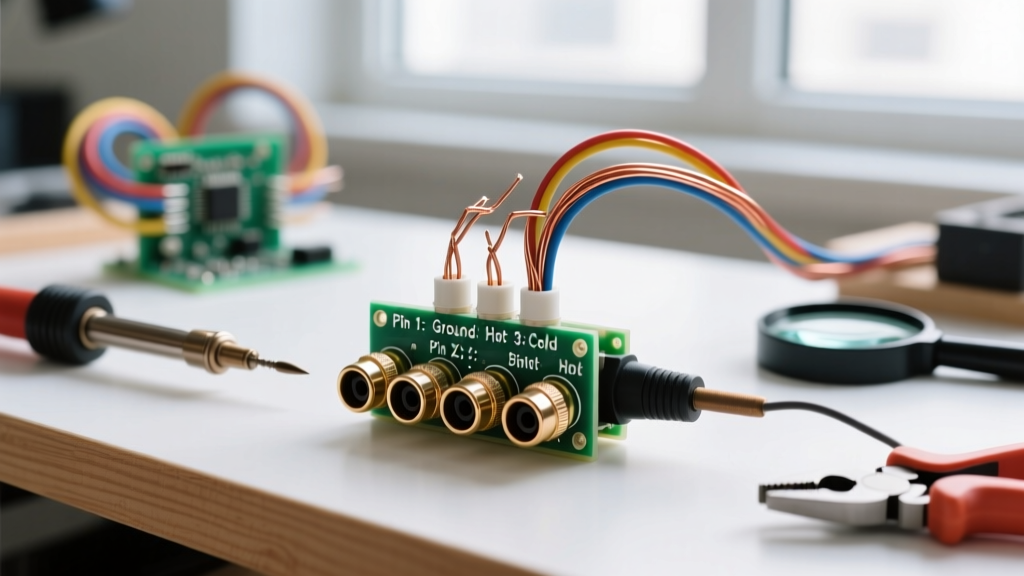
The Audio Engineering Society (AES) and the International Electrotechnical Commission (IEC 61076-2-103) dictate the global standard for balanced analog audio. When looking at the solder side (the back) of a male XLR connector, or the face of a female connector, the pinout is as follows:
Standard Balanced Audio Pinout
- Pin 1: Ground / Shield (Chassis)
- Pin 2: Hot (+) / Non-inverting phase
- Pin 3: Cold (-) / Inverting phase
Pro Tip: Always verify Pin 2 as "Hot". While vintage equipment from the 1970s (like early Shure or Telefunken gear) sometimes used Pin 3 as Hot, the modern AES-148 standard strictly mandates Pin 2 Hot. Wiring a Pin 3 Hot cable into a modern system will result in phase cancellation when summed with other microphones.
Terminating Star Quad Cable (Canare L-4E6S & Mogami W2534)
In environments with high electromagnetic interference (EMI), such as stages with heavy lighting rigs or near power distribution, standard 3-conductor cable is insufficient. Professionals use Star Quad cable, which contains four inner conductors twisted in a star pattern, plus a braided shield. The geometry ensures that any induced interference is distributed equally across all four conductors, allowing the differential amplifier at the preamp to reject it entirely.
Star Quad XLR Wiring Diagram
Because you have four conductors but only three XLR pins, you must pair them up:
- Pin 1 (Ground): Bare copper shield drain wire.
- Pin 2 (Hot): Twist and solder the two Blue (or White) conductors together.
- Pin 3 (Cold): Twist and solder the two White (or Red) conductors together.
Note: Always check the manufacturer's datasheet for your specific Star Quad cable, as color coding varies between Canare, Mogami, and Belden.
5-Pin XLR Soldering Diagrams: DMX512 vs. Stereo Audio
While 3-pin XLRs dominate audio, 5-pin XLRs are standard for lighting control (DMX512-A) and specialized stereo/intercom applications. It is a critical safety and operational rule to never use standard 3-pin microphone cables for DMX lighting, as the impedance mismatch (110-ohm for DMX vs. 45-75-ohm for audio) causes signal reflection and erratic fixture behavior.
| Pin Number | 3-Pin Audio (AES) | 5-Pin DMX512-A (ESTA) | 5-Pin Stereo Audio |
|---|---|---|---|
| Pin 1 | Shield / Ground | Shield / Ground | Shield / Ground |
| Pin 2 | Hot (+) | Data 1 - (Primary) | Left Channel Hot (+) |
| Pin 3 | Cold (-) | Data 1 + (Primary) | Left Channel Cold (-) |
| Pin 4 | N/A | Data 2 - (Secondary) | Right Channel Hot (+) |
| Pin 5 | N/A | Data 2 + (Secondary) | Right Channel Cold (-) |
For authoritative standards on lighting protocols, refer to the Entertainment Services and Technology Association (ESTA) guidelines regarding ANSI E1.11 DMX512-A.
Essential Tools for Flawless XLR Termination
To achieve IPC-J-STD-001 compliant solder joints on XLR connectors, you need precise thermal control. A cheap, unregulated soldering iron will melt the nylon insert and ruin a $12 Neutrik connector.
- Soldering Station: Hakko FX-888D or Weller WE1010. Set to 360°C (680°F) for leaded solder, or 380°C (716°F) for lead-free.
- Solder Wire: 60/40 Sn/Pb Rosin Core (e.g., Kester 44, 0.031" diameter) for the easiest flow, or Sn96.5/Ag3.0/Cu0.5 (e.g., Kester 275) for RoHS-compliant lead-free environments.
- Wire Strippers: Knipex 12 62 180 or Ideal Industries Reflex. Precision is vital to avoid nicking the copper strands.
- Flux: Amtech NC-559 or MG Chemicals 8341 no-clean tacky flux. Essential for Star Quad multi-strand twisting.
- Heat Shrink (Optional): 3/32" polyolefin tubing for insulating the shield wire if the connector lacks an internal ground lug.
Step-by-Step XLR Soldering Procedure
Follow this exact sequence to ensure mechanical strength and electrical continuity without damaging the connector.
1. Preparation and Stripping
Slide the XLR shell and strain relief boot onto the cable before doing anything else. Strip the outer cable jacket exactly 20mm (approx. 3/4 inch). Strip the individual conductors to 4mm. If using Star Quad, twist the paired conductors tightly and apply a tiny amount of flux before tinning them with solder.
2. Tinning the Solder Cups
Apply the iron tip to the outside of the XLR solder cup for 1 second, then feed 2mm of solder into the cup. Remove the solder, then the iron. The cup should be filled halfway with a shiny, concave fillet. Do not overfill, or you will create a solder bridge between Pin 2 and Pin 3.
3. The Soldering Sequence (Crucial)
Always solder in this specific order to manage heat dissipation:
- Pin 1 (Ground): Solder this first. Pin 1 is often physically connected to the metal shell or a large ground plane, acting as a massive heat sink. It requires the most heat and time.
- Pin 3 (Cold): Solder the negative signal wire next.
- Pin 2 (Hot): Solder this last. By the time you reach Pin 2, the plastic insert will be warm. Soldering Pin 2 first increases the risk of melting the plastic divider between Pin 2 and Pin 3, causing a short circuit.
For each pin, insert the tinned wire into the cup, apply the iron to the side of the cup and the wire simultaneously for 1.5 to 2 seconds, and remove. The joint should be shiny and smooth. A dull, grainy joint indicates a "cold joint" caused by movement during cooling.
4. Assembly and The "Chuck Test"
Slide the insert back into the shell. Ensure the keying notch aligns perfectly. Tighten the setscrew (if applicable) and thread the strain relief boot. Perform the "Chuck Test": grip the cable firmly and pull with about 15 lbs of force. The jacket should be gripped by the strain relief, and zero tension should transfer to the solder cups.
Advanced Troubleshooting and Failure Modes
Even experienced techs encounter issues. Here is how to diagnose and fix the most common XLR termination failures.
Ground Loops and the "Pin 1 Lift"
In complex PA systems connecting multiple powered speakers and mixing consoles, connecting the shield (Pin 1) at both ends can create a ground loop, resulting in a persistent 50/60Hz hum. The standard fix is a Pin 1 Lift—intentionally leaving Pin 1 disconnected at the source (output) end of the cable, while keeping it connected at the destination (input) end. Alternatively, use Neutrik connectors with the built-in ground lift switch to isolate the shell from Pin 1 without breaking the continuous shield path inside the cable.
Melted Inserts and Solder Bridges
If your multimeter shows continuity between Pin 2 and Pin 3, you have a solder bridge. This is almost always caused by overfilling the cups or using an iron set above 400°C, which melted the plastic barrier. Fix: Use solder wick (desoldering braid) with liquid flux to pull the excess solder out of both cups, clean with isopropyl alcohol, and re-solder at a lower temperature.
Intermittent Signal (The "Crackle")
If the audio crackles when the cable is wiggled near the boot, the strain relief is failing to grip the outer jacket. This means you stripped too much jacket off, leaving the delicate inner conductors to bear the mechanical pulling force. The only fix is to cut the connector off and start over with the correct 20mm strip length.
Conclusion
Mastering the XLR soldering diagram is a foundational skill for any audio engineer, AV technician, or DIY enthusiast. By adhering to the AES pinout standards, utilizing Star Quad configurations in noisy environments, and respecting the thermal limits of the connector inserts, you will build cables that deliver pristine, noise-free audio for decades. For further reading on audio interconnection standards, consult the Audio Engineering Society (AES) publications and verify physical connector wiring via the official Neutrik wiring diagram support page.