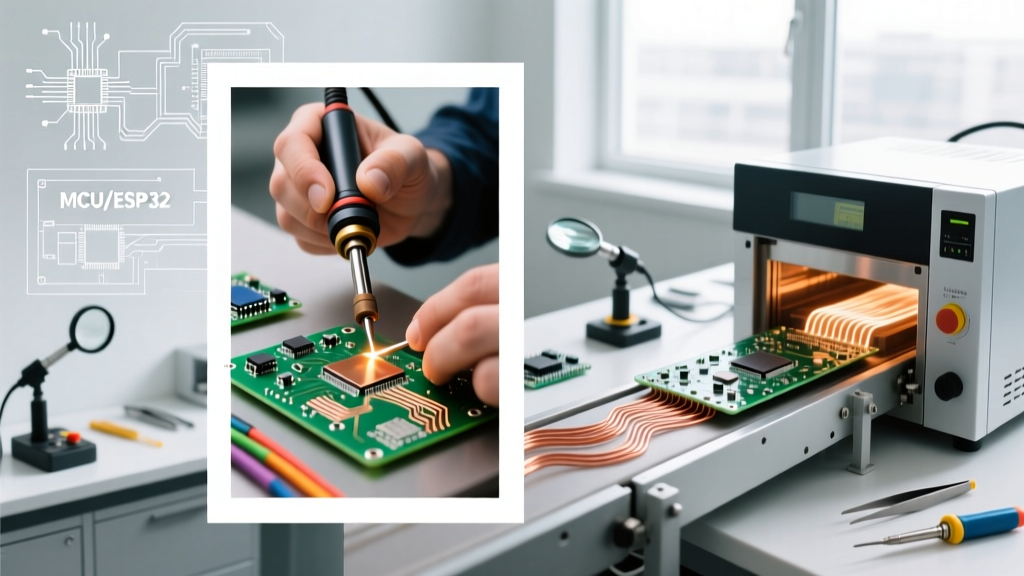

The Core Contenders: Manual vs. Automated Soldering Process
When transitioning from breadboard prototypes to custom printed circuit boards (PCBs) in 2026, makers and small-batch manufacturers face a critical decision: which soldering process yields the highest reliability for the lowest cost? While industrial facilities rely on automated selective soldering and massive convection ovens, the DIY and prosumer space has evolved dramatically. Today, the debate primarily centers on precision hand soldering versus small-batch reflow soldering.
According to the IPC standards for electronic assemblies, the reliability of a solder joint is dictated by proper wetting, intermetallic compound (IMC) formation, and thermal profiling. Let us dissect the metallurgy, economics, and failure modes of both methods to determine which approach fits your next project.
Method 1: The Manual Soldering Process
Equipment and Thermal Dynamics
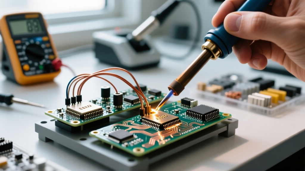
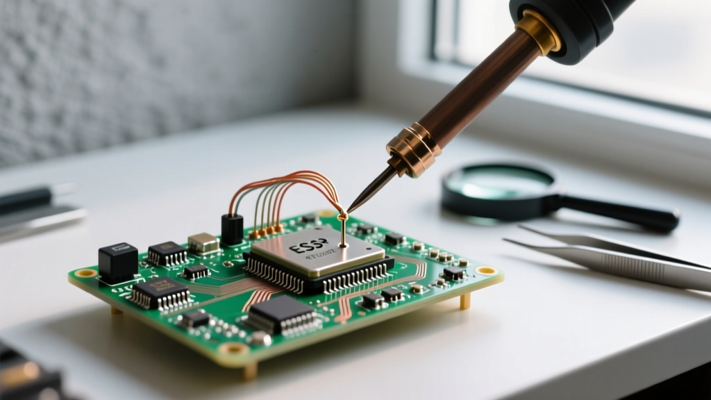
Hand soldering remains the cornerstone of through-hole technology (THT) and low-density surface mount device (SMD) rework. A high-quality station like the Hakko FX-951 (retailing around $230) or the Weller WE1010NA ($115) utilizes active tip temperature sensing. When the tip touches a copper pad, the thermal mass draws heat away; the station's microcontroller detects the resistance drop and injects current to maintain the setpoint.
- Optimal Tip Geometry: For 0603 or 0805 SMD components, a 45-degree micro-chisel (e.g., Hakko T15-C1) maximizes surface area contact, ensuring rapid heat transfer without localized scorching.
- Flux Activation: Manual soldering relies heavily on the flux core within the wire. For Sn63/Pb37 (eutectic), the rosin activates around 150°C, cleaning oxides before the 183°C liquidus point is reached.
- Advanced Cartridge Systems: For heavy ground planes, cartridge-based systems like the JBC CD-2BQE ($400+) offer near-instantaneous thermal recovery, dropping the tip temperature directly into the joint rather than relying on conduction through a long shaft.
Method 2: The Reflow Soldering Process
Paste Deposition and Smart Hotplates
Reflow soldering is the undisputed champion for high-density SMD boards featuring QFN packages or 0402 passives. The process involves applying Type 4 or Type 5 solder paste through a laser-cut stainless steel stencil (typically 0.1mm thick for fine-pitch components). In 2026, the market has shifted away from makeshift toaster ovens toward precision smart hotplates like the Pine64 MHP50 ($59) or the Atten ST-862D hot air station used for localized reflow.
"The transition to lead-free SAC305 alloys in commercial manufacturing requires peak reflow temperatures of 245°C, pushing the thermal limits of budget FR-4 substrates and making precise thermal profiling non-negotiable." — Indium Corporation Solder Alloy Data
Comparative Matrix: Cost, Speed, and Defect Rates
| Parameter | Manual Soldering Process | Reflow Soldering Process |
|---|---|---|
| Setup Cost (2026) | $115 - $250 (Station + Tips) | $150 - $400 (Stencil, Paste, Hotplate) |
| Time per Board (50 SMD parts) | 35 - 45 minutes | 10 minutes (excluding stencil alignment) |
| Primary Defect Risk | Cold joints, pad lift, thermal damage | Tombstoning, solder bridging, voiding |
| Best Application | THT, mixed-technology, single prototypes | Dense SMD, QFN/BGA, batches of 10+ |
Thermal Profiling: The 4 Stages of Reflow
Understanding the thermal profile is where most DIYers fail when adopting the reflow soldering process. A proper profile is not just "heating until it melts." It requires four distinct phases to ensure the IMC layer forms correctly at a thickness of 1 to 3 microns:
- Preheat (Ramp): Gradually raising the ambient temperature from 25°C to 150°C at a rate of 1°C to 3°C per second. Ramping too fast causes solvent spattering in the paste, leading to micro-solder balls.
- Thermal Soak: Holding between 150°C and 200°C for 60 to 90 seconds. This allows the board's thermal mass to equalize and ensures the flux fully activates to strip metal oxides.
- Reflow (Peak): Pushing past the liquidus temperature (217°C for SAC305) to a peak of 235°C–245°C. The time above liquidus (TAL) should be strictly maintained between 45 and 90 seconds to form a robust intermetallic layer without degrading the component packaging.
- Cooling: A controlled descent (typically 2°C to 4°C per second) to prevent thermal shock and ensure a fine-grain crystalline structure in the solidified joint.
Real-World Failure Modes and Edge Cases
Tombstoning in Reflow
Tombstoning (or the "drawbridge effect") occurs when one end of a passive component lifts off the pad during the reflow soldering process. This is almost always caused by uneven heating across the component. If the left pad reaches the paste's liquidus point before the right pad, the wetting force on the left side pulls the component upright. Solution: Ensure your hotplate or oven has uniform thermal distribution, and use a thermal soak phase to equalize pad temperatures before the final ramp.
Cold Joints and Oxidation in Hand Soldering
According to NASA Workmanship Standards, a proper solder fillet must exhibit a smooth, concave transition with visible wetting. A dull, lumpy, or convex joint indicates a cold joint. In 2026, with the widespread use of lead-free alloys that do not flow as easily as legacy tin-lead, cold joints are rampant. Solution: Apply liquid no-clean flux (e.g., Amtech NC-559) to the pads before applying the iron, and ensure your tip is tinned and free of carbonized flux residue.
Expert Verdict: Matching the Process to Your Workflow
There is no universal "best" method; the optimal soldering process depends entirely on your component density and batch size. If you are assembling a mixed-signal board with heavy power connectors and a few SOIC chips, a high-end manual station like the JBC CD-2BQE is unmatched in versatility. However, if you are iterating on a dense IoT sensor node featuring a 48-pin QFN microcontroller and dozens of 0402 decoupling capacitors, investing in laser-cut stencils and a PID-controlled reflow hotplate will save you hours of frustration and yield vastly superior, reproducible results.
Frequently Asked Questions
Can I use a standard kitchen skillet for the reflow soldering process?
While technically possible for low-temperature tin-bismuth pastes, using a kitchen skillet for SAC305 lead-free paste is highly discouraged. Skillets lack PID temperature control, making it nearly impossible to manage the critical thermal soak and cooling ramp rates, leading to brittle joints and damaged PCB substrates.
Does solder paste expire?
Yes. Type 4 and Type 5 SMD solder pastes contain volatile flux solvents. If left unrefrigerated or used past their 6-to-12-month shelf life, the flux dries out, resulting in severe oxidation, poor wetting, and excessive solder balling during the reflow process.