
The Core Contenders in Modern PCB Assembly
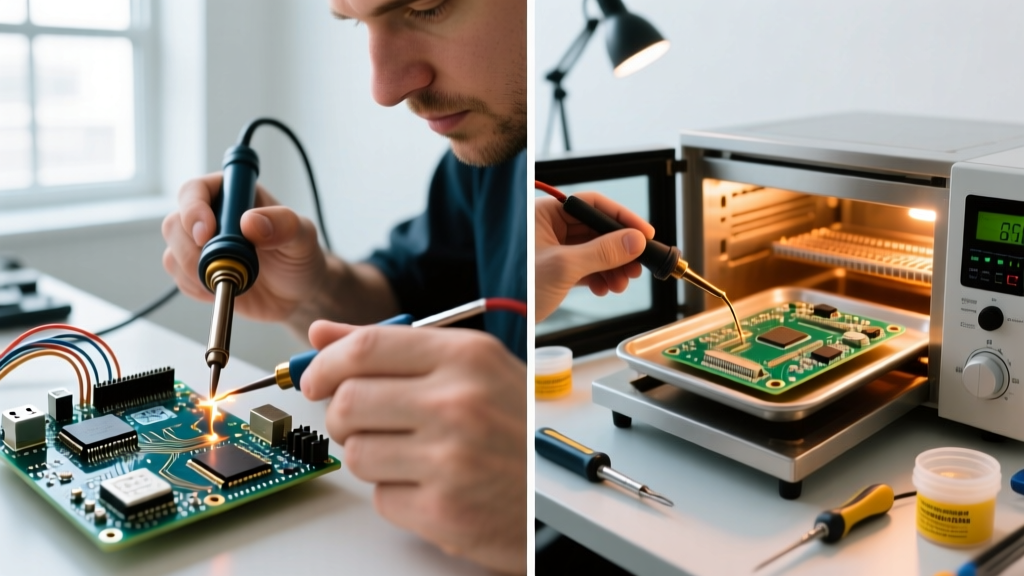
As surface-mount technology (SMT) continues to dominate electronic design, the traditional through-hole approach has largely given way to dense, miniaturized components. For hobbyists, prototyping labs, and small-batch manufacturers, mastering pcb board soldering requires a critical decision: do you stick with the tactile control of a precision soldering iron, or do you transition to solder paste reflow techniques? Both methods have distinct metallurgical requirements, cost structures, and defect profiles. In this comprehensive method comparison, we break down the physics, economics, and practical realities of hand soldering versus paste reflow to help you choose the right setup for your workbench in 2026.
Method 1: Precision Hand Soldering (The Iron Approach)
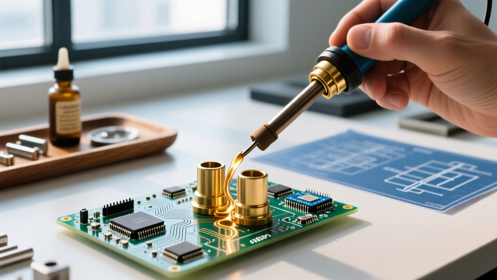
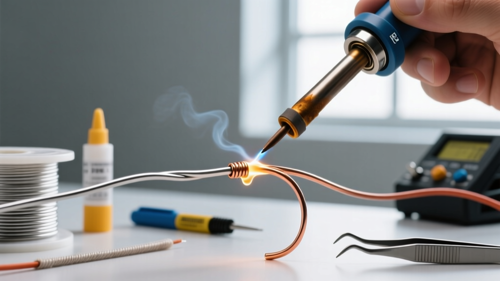
Hand soldering remains the bedrock of electronics prototyping. It is highly effective for through-hole components, large SMD passives (0805, 1206), and integrated circuits with generous lead pitches (SOIC, SOP). However, as component sizes shrink to 0402 and 0201, or when dealing with hidden thermal pads (QFN, BGA), the physical limits of a soldering iron tip become apparent.
Essential Equipment and Metallurgy
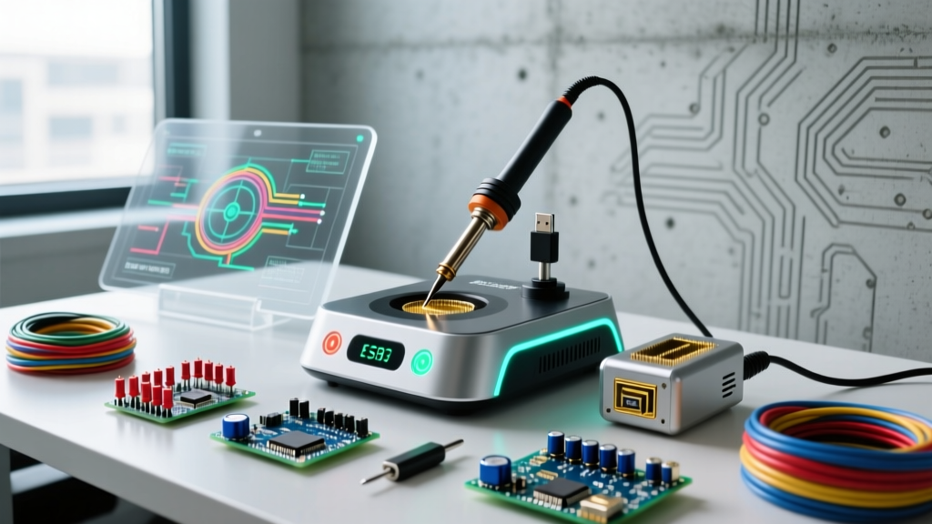
The modern hand-soldering workstation relies on rapid thermal recovery rather than sheer wattage. The Hakko FX-951 (approximately $235) utilizes T12 cartridge tips where the heating element and sensor are integrated into the tip itself, achieving 350°C in under 8 seconds. Alternatively, the Weller WE1010NA ($115) offers a budget-friendly entry point with reliable ET-series tip compatibility.
- Tip Geometry: Avoid conical tips entirely; they offer minimal surface area for thermal transfer. A 1.6mm or 2.4mm chisel tip (D-shape) is optimal for dragging solder across IC pins, while a micro-Knife (K-tip) excels at precision pad cleaning and drag-soldering fine-pitch 0.5mm TQFP packages.
- Solder Alloy: For hand soldering, Sn63/Pb37 (eutectic) remains the undisputed champion for DIY and prototyping. Melting at a sharp 183°C, it transitions instantly from liquid to solid, eliminating the "plastic" (mushy) state found in lead-free alloys like SAC305. This prevents cold joints caused by micro-vibrations during the cooling phase. Kester 245 (0.025" diameter) with a mildly activated rosin (RMA) flux core is the industry benchmark.
- Flux Chemistry: Even with flux-core wire, additional liquid or tacky flux is mandatory for SMD rework. Amtech NC-559-V2-TF is a no-clean, tacky flux that provides excellent wetting and prevents bridging on fine-pitch components.
Method 2: Solder Paste Reflow (The SMT Standard)
Reflow soldering is the process of applying solder paste to PCB pads, placing components, and heating the entire assembly until the paste melts and forms intermetallic bonds. This is the only viable method for high-density boards, QFNs, BGAs, and 0402/0201 passives.
The Reflow Ecosystem
Transitioning to reflow requires a paradigm shift from point-heating to whole-board thermal profiling. The setup involves three critical stages: stenciling, pick-and-place, and thermal reflow.
- Stencils and Paste: A laser-cut stainless steel stencil (typically $15–$30 via services like OSH Stencils or JLCPCB) is required to apply paste evenly. For standard 0603 and SOIC components, Type 3 solder paste (20-45μm powder size) like Chip Quik SMD291AX ($38 for a 35g syringe) is sufficient. For 0402 components and 0.4mm BGA pitches, you must upgrade to Type 4 paste (15-25μm) to prevent stencil aperture clogging and bridging.
- Thermal Sources: While DIY hotplates (like the Aoyue 853A at $130) work for single-sided boards, they struggle with 4-layer boards featuring heavy internal copper pours, leading to board warping and uneven heating. As of 2026, affordable desktop convection reflow ovens (such as the Whizoo Smart Reflow Oven, ~$140) utilize forced air and programmable thermal profiles to ensure uniform heating across complex multilayer boards.
Understanding the Thermal Profile
Reflow is not simply "heating the board until it melts." According to the IPC J-STD-001 standard for soldered electrical assemblies, a proper lead-free reflow profile consists of four distinct zones:
Ramp: Heating from ambient to 150°C at a maximum rate of 2°C/sec to prevent solvent boiling and solder splatter.
Soak: Holding at 150°C–170°C for 60–90 seconds to activate the flux and equalize temperatures across components of varying thermal mass.
Reflow: Spiking to a peak of 235°C–245°C for 30–60 seconds to achieve proper intermetallic layer formation.
Cooling: A controlled descent to prevent thermal shock to ceramic capacitors.
Head-to-Head: Method Comparison Matrix
To visualize the operational differences, refer to the comparison matrix below. Data reflects typical small-batch prototyping environments.
| Parameter | Precision Hand Soldering | Solder Paste Reflow |
|---|---|---|
| Initial Setup Cost | $115 – $250 (Iron, brass sponge, flux) | $180 – $350 (Stencil, paste, hotplate/oven) |
| Time per Board (50 SMD pads) | 30 – 45 minutes | 10 – 15 minutes (excluding stencil prep) |
| Component Limitations | Fails on BGA, QFN, and <0603 passives | Handles all SMT components, including BGA |
| Through-Hole Capability | Excellent (Primary use case) | Poor (Requires selective wave or pin-in-paste) |
| Primary Defect Modes | Cold joints, lifted pads, flux residue burns | Tombstoning, solder balls, voiding, bridging |
| Scalability (10+ boards) | Low (High operator fatigue, inconsistent yields) | High (Batch processing, consistent yields) |
Analyzing Failure Modes: Where Things Go Wrong
Both methods introduce unique failure modes that require specific troubleshooting strategies. Understanding these is crucial for passing IPC-A-610 Class 2 visual inspection standards.
Hand Soldering Defects
- Cold Joints: Characterized by a dull, grainy appearance. Caused by insufficient heat transfer to the pad (not the lead) or moving the component before the eutectic alloy fully crystallizes. Fix: Apply the iron tip to the pad and lead simultaneously for 2 seconds, feed solder to the pad, and remove.
- Lifted Pads: Excessive dwell time (over 5 seconds) with a high-wattage iron delaminates the copper from the FR4 substrate. Fix: Use active tips (T12/T15) that recover heat instantly, allowing for sub-3-second joints.
Reflow Defects
- Tombstoning: A passive component stands on one end during reflow. This occurs when one pad reaches the solder's liquidus temperature before the other, creating an asymmetric wetting force that pulls the component upright. Fix: Ensure symmetrical thermal relief routing in your PCB CAD software and verify your reflow oven's airflow is balanced.
- Solder Balls (Splatter): Tiny spheres of solder form around the pads. This is almost always caused by ramping the temperature too quickly in the first stage of reflow, causing the volatile solvents in the flux to boil explosively. Fix: Extend the pre-heat/ramp time.
- Voiding under QFNs: Flux gases become trapped under large thermal pads, creating voids that compromise thermal conductivity. Fix: Use a "windowed" stencil aperture design (dividing the thermal pad paste deposit into four smaller squares) to provide escape routes for off-gassing.
The Hot Air Rework Station: A Hybrid Alternative?
Sitting between the iron and the reflow oven is the hot air rework station, such as the Quick 861DW ($260). While some attempt to use hot air for full-board initial assembly by flooding the board with paste and blasting it with air, this is highly discouraged. Hot air creates localized temperature gradients that guarantee tombstoning and can easily melt adjacent plastic connectors. Hot air should be strictly reserved for rework and desoldering—removing defective QFNs, replacing SOIC chips, or shrinking polyolefin heat shrink tubing. It is a complementary tool, not a primary assembly method.
Decision Framework: Which Method Should You Buy Into?
Choosing the right pcb board soldering method depends entirely on your design complexity and production volume. As highlighted in resources like SparkFun's SMD Soldering Tutorial, matching your tool to the component footprint is the key to manufacturing success.
Choose Hand Soldering If:
- Your designs consist primarily of through-hole components or large SMDs (0805, SOIC-8, TQFP-32 with 0.8mm pitch).
- You are building one-off prototypes where the 3-day lead time and cost of ordering a custom stainless-steel stencil are unjustified.
- You frequently need to modify, jumper, or rework existing boards on the fly.
Choose Paste Reflow If:
- Your PCBs feature QFNs, BGAs, or high-density passives (0402/0201).
- You are producing small batches (10 to 50 units) where operator fatigue and inconsistent hand-soldering yields become a bottleneck.
- You are designing 4-layer boards with heavy internal ground planes that act as massive heat sinks, making hand soldering large connectors nearly impossible without a pre-heater.
Summary
Ultimately, the most advanced electronics workbenches do not choose one over the other; they integrate both. A high-quality T12 soldering station handles the through-hole headers, connectors, and delicate wires, while a desktop convection oven and precision stencils handle the dense SMT core of the board. By understanding the metallurgical limits of Sn63/Pb37 wire versus Type 4 SAC305 paste, and respecting the thermal profiles dictated by industry standards, you can drastically reduce your defect rate and produce commercial-grade assemblies right from your own lab.