
From Rigid Bulbs to Flexible Circuits: A Historical Overview
The practice of led light strip soldering has undergone a radical transformation over the last two decades. What began as a clumsy process of wiring rigid, through-hole components to makeshift backboards has evolved into a highly precise micro-soldering discipline. Today's high-density Chip-on-Board (COB) strips and ultra-compact addressable SMDs (Surface Mount Devices) demand a fundamental understanding of thermal dynamics, flexible substrate material science, and specialized low-temperature alloys. For DIY enthusiasts and professional installers alike, understanding this evolution is not just an exercise in nostalgia; it is critical for avoiding catastrophic pad delamination and integrated circuit (IC) thermal death in modern lighting projects.
The Genesis: 5mm DIP LEDs and the Mechanical Fragility Era
In the early 2000s, commercial 'LED strips' were essentially rigid fiberglass (FR4) PCBs populated with 5mm Dual In-line Package (DIP) LEDs. Because these components featured long wire leads that passed entirely through the board, the soldering process itself was forgiving. A standard 40W RadioShack iron with a chisel tip, set to a crude 380°C, could easily flow 63/37 tin-lead solder onto the thick copper pads without damaging the LED die.
However, the failure mode was rarely the solder joint itself. The primary point of failure was mechanical. The rigid FR4 boards had to be snapped along scored lines to fit dimensions, and the heavy 22 AWG solid-core wires used to bridge gaps created immense leverage on the solder pads. Vibration and thermal expansion caused the pads to rip cleanly off the board. The industry quickly realized that for lighting to be truly versatile, the substrate itself had to bend.
The Material Shift: Polyimide FPCBs and Thermal Mass Challenges
The introduction of Flexible Printed Circuit Boards (FPCBs) revolutionized the industry. Manufacturers transitioned from rigid fiberglass to polyimide (often known by the brand name Kapton) and flexible copper-clad laminates. While this allowed strips to bend around 90-degree corners and wrap around columns, it introduced a massive thermal challenge for led light strip soldering.
Polyimide is highly heat resistant, but the adhesive bonding the copper traces to the polyimide base is not. When early DIYers applied standard 350°C soldering irons to the microscopic SMD pads of 3528 and 5050 LED strips, the localized heat transferred instantly through the thin copper. Within two seconds, the adhesive would boil, causing the copper pad to delaminate and lift off the strip permanently. This era forced a shift toward temperature-controlled soldering stations and the strict enforcement of the 'two-second dwell time' rule.
| Era | Dominant LED Tech | Substrate Material | Primary Soldering Challenge | Ideal Tooling |
|---|---|---|---|---|
| Early 2000s | 5mm DIP Through-Hole | Rigid FR4 / Aluminum | Mechanical stress, bulky wire leverage | 40W-60W Ungrounded Irons |
| 2010-2015 | SMD 3528 / 5050 | Polyimide FPCB | Pad delamination, adhesive boiling | Temp-Controlled T12 Stations |
| 2016-2021 | WS2812B / SK6812 Addressable | FPCB with Embedded ICs | IC thermal death, data pad lifting | Micro-tips, fine flux pens |
| 2022-2026 | High-Density COB / 2020 SMD | Silicone-Coated FPCB | 1.5mm pitch clearance, silicone melting | Low-temp paste, JBC C115 tips |
The Addressable Revolution and Thermal Sensitivity
The mid-2010s brought the addressable LED revolution, spearheaded by the WS2812B (NeoPixel) and later the SK6812 RGBW chips. Unlike standard analog strips where cutting and soldering only involved bridging 12V/24V and Ground, addressable strips required soldering a 5V Data-In and Data-Out line connected directly to a microscopic, highly heat-sensitive CMOS control IC embedded inside the LED package.
Expert Insight: According to Adafruit's NeoPixel Überguide, the internal wire bonds connecting the silicon die to the external pads inside a WS2812B can degrade or detach if subjected to prolonged heat. Soldering the data line requires extreme precision; a dwell time exceeding 1.5 seconds at 320°C can permanently brick the pixel, breaking the data chain for every subsequent LED on the strip.
This era necessitated the use of high-quality, fast-recovering soldering tips. Hobbyists began abandoning cheap ceramic heaters in favor of direct-drive T12 and T245 cartridge stations. The ability of a T12 tip to detect a thermal drop and inject current directly into the tip core meant the iron could maintain a steady 280°C without overshooting, drastically reducing the risk of frying the addressable ICs.
Mastering the Micro-Pitch: The Modern COB Era
As we look at the landscape in 2026, Chip-on-Board (COB) technology and ultra-compact 2020-package addressable LEDs dominate the premium market. COB strips feature hundreds of microscopic, un-packaged LED dies encapsulated in a continuous phosphor/silicone layer to eliminate 'light spotting.' The solder pads on these strips are incredibly small, often spaced at a mere 1.5mm to 2.0mm pitch.
Traditional 63/37 tin-lead solder wire (melting point 183°C) requires iron temperatures around 300°C to 320°C to flow properly. At these temperatures, the heat radiates laterally and melts the adjacent silicone diffuser coating, ruining the strip's aesthetic and structural integrity. Furthermore, as noted in SparkFun's SMD Soldering Tutorial, bridging adjacent pads on sub-2mm pitches is a common failure mode when using standard solder wire and bulky chisel tips.
The Low-Temperature Solder Revolution
To solve the thermal limitations of modern high-density strips, the DIY and professional lighting communities have widely adopted Bismuth-based low-temperature solder alloys. The most prominent is Sn42/Bi58 (42% Tin, 58% Bismuth), which boasts a eutectic melting point of just 138°C (280°F).
By utilizing Sn42/Bi58 solder paste applied via a micro-syringe, technicians can set their soldering stations to a mere 150°C to 160°C. This provides enough thermal delta to reflow the paste instantly while keeping the overall temperature far below the degradation threshold of polyimide adhesives, silicone diffusers, and sensitive addressable ICs. While a 10g syringe of high-quality Sn42/Bi58 paste costs around $18-$25 (compared to $5 for a roll of standard wire), the reduction in scrapped, heat-damaged COB strips makes it an essential investment for modern led light strip soldering.
Essential Tooling for 2026 FPCB Soldering
If you are transitioning from older analog strips to modern addressable or COB architectures, your toolbench must evolve. Here is the current standard for professional-grade FPCB work:
- Soldering Station: JBC CD-2BQE or Pinecil V2 (Smart Iron). The Pinecil V2 ($26) offers incredible value with rapid PD-triggered heating, while the JBC ($450+) remains the undisputed industry standard for thermal recovery.
- Tip Geometry: JBC C115-110 (0.1mm micro-conical) or equivalent T115 nano-tips. These allow you to touch a single 0.8mm pad without grazing the adjacent ground plane.
- Flux: Chip Quik NC191RM or Amtech NC-559-V2-TF tacky flux. Liquid flux pens evaporate too quickly under modern micro-tips; tacky flux holds the SMD components in place and promotes capillary action.
- Magnification: A digital microscope (like the Andonstar AD409 Pro, ~$250) or a high-quality optical trinocular boom stand. Naked-eye soldering on 1.5mm pitch COB strips consistently results in cold bridges.
Step-by-Step Protocol for Modern Addressable FPCBs
To synthesize this historical evolution into actionable methodology, follow this exact protocol when splicing or terminating modern WS2812B or SK6812 flexible strips:
- Preparation: Score the FPCB precisely on the copper cut-line using a fresh scalpel blade. Do not use scissors, as the shearing force will micro-fracture the internal copper traces.
- Stripping & Tinning: Use 28 AWG silicone-stranded wire. Strip exactly 2mm of insulation and pre-tin the wires with standard Sn63/Pb37 solder.
- Flux Application: Apply a microscopic dab of tacky flux to the exposed FPCB pads. This is non-negotiable for preventing pad lift.
- Station Calibration: Set your T12/T245 station to 280°C. Use a micro-conical tip. Clean the tip on brass wool, not a wet sponge (which causes thermal shock and micro-cracks in the tip plating).
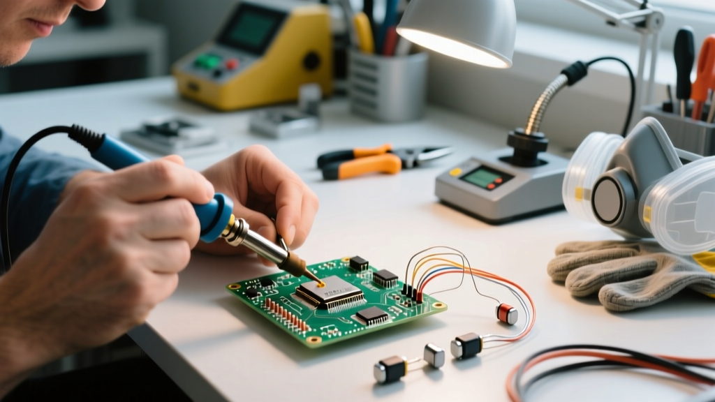
- The 'Touch-and-Lift' Technique: Hold the pre-tinned wire to the fluxed pad. Touch the iron to the wire—not the pad—for exactly 1 to 1.5 seconds. The heat will transfer through the wire and reflow the joint. Remove the iron immediately, holding the wire still for 2 seconds while the joint crystallizes.
By respecting the material science and thermal limits that dictated the evolution of LED technology, you ensure robust, long-lasting connections that honor the engineering marvel of modern flexible lighting.