
Beyond Metallic Glue: The True Physics of Soldering
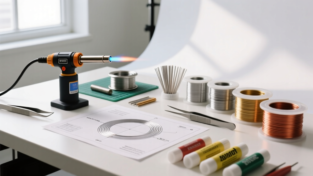
When beginners ask, "what does soldering do?", the most common misconception is that solder acts as a conductive glue binding two metals together. In reality, soldering is a complex metallurgical process. It does not merely stick components to a board; it creates an intermetallic compound (IMC) at the molecular level. Understanding this distinction is critical when deciding whether to solder, crimp, wire-wrap, or use conductive adhesives for your next electronics project in 2026.
In this comprehensive method comparison, we break down the exact metallurgical mechanics of soldering and stack it against alternative joining methods. Whether you are building high-vibration drone flight controllers or prototyping low-power IoT sensors, choosing the right electrical joining method dictates the longevity, signal integrity, and mechanical resilience of your assembly.
The Metallurgy: What Does Soldering Do at a Microscopic Level?
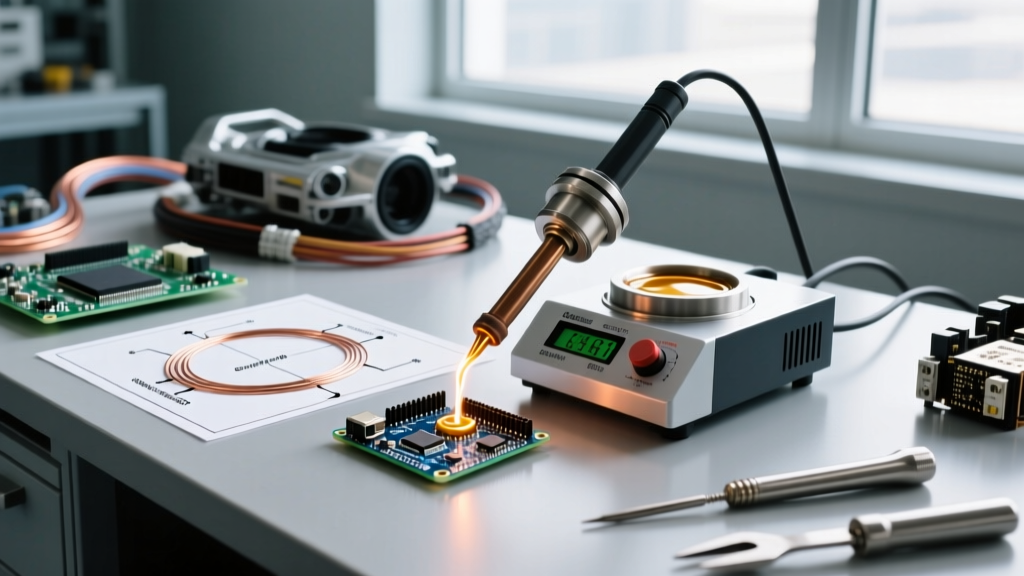
When you apply a soldering iron tip (typically set between 320°C and 380°C for lead-free alloys) to a copper pad, the base metals do not melt. Instead, the filler metal—such as the industry-standard SAC305 (Sn96.5/Ag3.0/Cu0.5)—melts at 217°C.
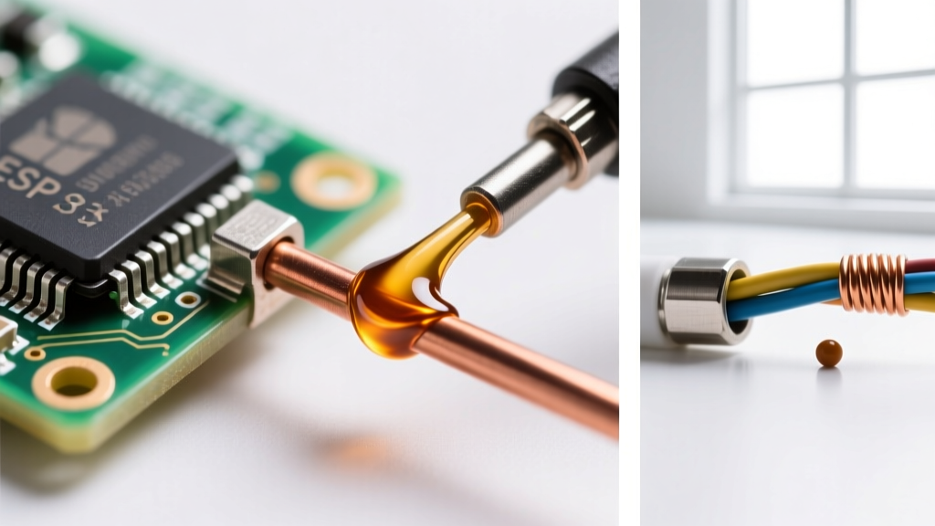
Once liquid, the molten solder dissolves a microscopic layer of the copper substrate. This triggers a metallurgical reaction, forming a distinct intermetallic layer, primarily Cu6Sn5 (eta phase) and Cu3Sn (epsilon phase). This IMC layer is what actually creates the electrical and mechanical bond. According to the IPC J-STD-001 requirements for soldered electrical assemblies, a proper wetting angle and a continuous IMC layer are the definitive markers of a reliable joint.
The Role of Flux in the Soldering Process
Soldering cannot occur in the presence of oxidation. This is where flux intervenes. Fluxes categorized under IPC J-STD-004B (such as ROL0 or ROL1) contain activators that chemically strip copper oxide at high temperatures, allowing the molten solder to flow via capillary action. Without flux, surface tension causes the solder to ball up, resulting in a high-resistance cold joint.
Soldering vs. Crimping: Metallurgical vs. Mechanical Bonds
While soldering relies on thermal diffusion and IMC formation, crimping relies on plastic deformation. A crimp connection forces a terminal and a wire to deform into one another, creating a gas-tight, cold-welded mechanical bond without the application of heat.
Tooling and Cost Comparison
The barrier to entry for soldering is remarkably low. A highly reliable Hakko FX-888D digital soldering station costs approximately $110, and a spool of 63/37 eutectic solder is under $25. Conversely, professional crimping requires precision ratcheting tools to ensure consistent deformation. A Knipex 97 53 14 self-adjusting wire ferrule crimper retails for around $180, while specialized Mil-Spec Molex or TE Connectivity crimp dies can push tooling costs well past $400 per terminal series.
| Feature | Soldering (SAC305 / Sn63Pb37) | Crimping (Ratcheted Mechanical) |
|---|---|---|
| Bond Type | Metallurgical (Intermetallic Compound) | Mechanical (Plastic Deformation / Cold Weld) |
| Vibration Resistance | Moderate (Prone to fatigue cracking at IMC) | Exceptional (Passes MIL-STD-202 high-freq tests) |
| Thermal Stress | High (Risk of pad delamination on PCBs) | None (Cold process) |
| Reworkability | High (Desoldering wick / hot air rework) | Low (Terminals are single-use destructively removed) |
| Current Capacity | Limited by trace width and solder fillet volume | Extremely high (Used in automotive EV powertrains) |
When to Crimp: Automotive wiring, high-current battery packs, and aerospace harnesses where vibration would cause solder joints to micro-fracture. For deep-dive termination standards, refer to the TE Connectivity termination guidelines.
Soldering vs. Wire Wrapping: The Gas-Tight Alternative
Before surface-mount technology dominated, wire wrapping was the backbone of telecommunications and aerospace prototyping. Wire wrapping involves tightly coiling 30 AWG or 28 AWG solid-core silver-plated copper wire around a sharp, square-cornered terminal post using a specialized pneumatic or manual tool (like the OK Industries WSU-30M).
The Cold-Weld Phenomenon
What does soldering do that wire wrapping doesn't? Soldering introduces heat and flux residues. Wire wrapping, however, creates a gas-tight seal. The sharp corners of the terminal post bite into the silver-plated wire, displacing oxides and allowing the bare metals to fuse at room temperature. This cold-weld is impervious to corrosion and maintains stable contact resistance even in high-humidity environments. According to data published by the NASA Electronic Parts and Packaging (NEPP) Program, properly executed wire wraps exhibit superior longevity in low-outgassing vacuum environments compared to traditional flux-cored solder joints.
- Best for: High-reliability prototyping, vintage computer restoration, and aerospace backplanes.
- Drawbacks: Requires expensive specialized wire-wrap posts; not suitable for flexible or stranded wire; cannot be used for high-density surface-mount components.
Soldering vs. Conductive Epoxy: Heat-Sensitive Assembly
Sometimes, the heat required to form an intermetallic bond is exactly what will destroy your component. When assembling flexible printed circuits (flex PCBs), attaching heat-sensitive RF modules, or repairing delicate LCD glass substrates, soldering is a liability.
Enter silver-filled conductive epoxies, such as MG Chemicals 8331 (retailing at roughly $45 for a 50g dual-cartridge). These two-part adhesives cure at room temperature (or with mild 60°C acceleration) and provide a volume resistivity of approximately 0.0008 ohm-cm. While not as conductive as a pure SAC305 solder joint, conductive epoxies provide adequate electrical continuity for low-current signal traces while offering superior mechanical flexibility, preventing the solder joint cracking often seen on flex-PCB hinge points.
Press-Fit Technology: The Solderless PCB Standard
In modern high-speed telecom backplanes, soldering is increasingly being replaced by press-fit technology. Press-fit pins feature a compliant "eye-of-the-needle" geometry that deforms elastically when pushed into a plated through-hole (PTH). This creates a massive surface-area gas-tight connection without a single drop of solder, entirely eliminating the risk of solder voids, bridging, or thermal damage to multi-layer vias. Governed by the IPC-9752 standard, press-fit is the undisputed king of high-pin-count server motherboards.
Decision Framework: Which Method Should You Choose?
To determine what soldering should do for your specific project, use this rapid decision matrix:
- Choose Soldering for 90% of standard PCB assembly, through-hole components, and low-cost consumer electronics where automated reflow or manual iron work is economical.
- Choose Crimping for wire-to-wire connections, heavy-gauge power delivery, and environments subject to continuous mechanical vibration.
- Choose Wire Wrapping for zero-heat, high-reliability point-to-point prototyping on specialized backplanes.
- Choose Conductive Epoxy for flex circuits, heat-sensitive sensors, and applications requiring mechanical compliance.
Frequently Asked Questions
Does solder increase the mechanical strength of a joint?
No. Solder provides electrical continuity and secondary mechanical support. Relying on solder to bear physical weight (such as hanging a heavy transformer off a PCB solely by its soldered leads) will eventually lead to IMC layer fatigue and joint failure. Always use mechanical strain relief or adhesives for load-bearing components.
Why do my solder joints look dull and grainy?
If you are using lead-free SAC305, a slightly dull finish is normal due to the alloy's crystalline structure upon cooling. However, if using 63/37 eutectic solder, a dull or grainy joint indicates movement during the cooling phase or insufficient heat, resulting in a disturbed crystalline matrix that is prone to micro-cracking.