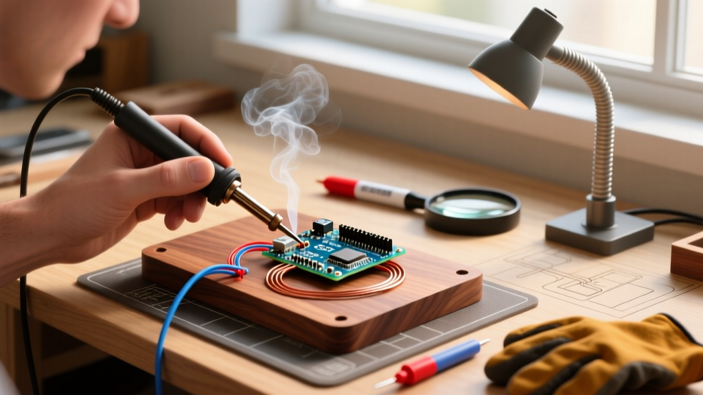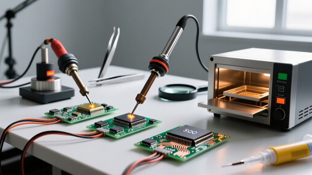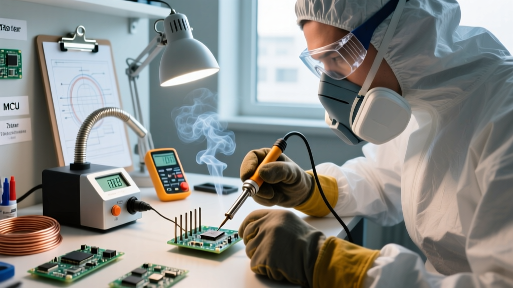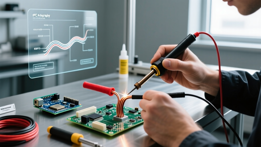

Defining the Bond: What Is Soldering?
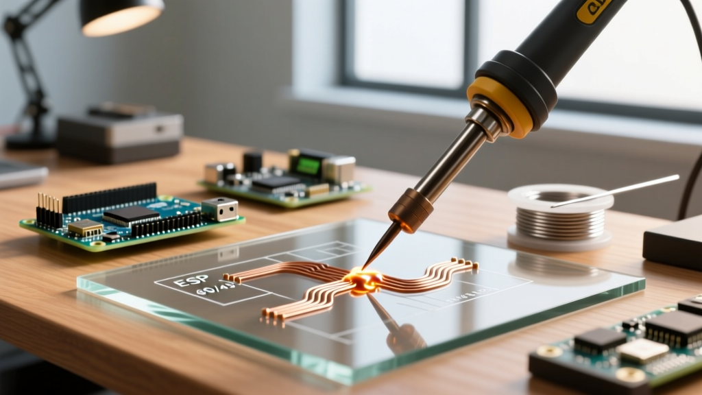
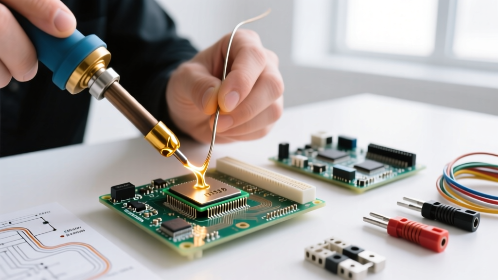
At its core, soldering is a metallurgical joining process where two or more metal surfaces are bonded using a filler metal (solder) that melts at a temperature below 450°C (842°F). Unlike welding, the base metals being joined do not melt. Instead, the molten solder wets the surfaces, dissolves a microscopic layer of the base metal, and forms an intermetallic compound (IMC) upon cooling.
According to the IPC (Association Connecting Electronics Industries), a proper solder joint requires optimal wetting—typically defined by a contact angle of less than 90 degrees between the solder and the base pad. But how does this thermal-chemical process stack up against purely mechanical joining methods like crimping, wire wrapping, or press-fit technology? For engineers, DIYers, and production managers in 2026, choosing the right termination method dictates the reliability, cost, and lifecycle of an electronic assembly.
The Metallurgy: Understanding the Intermetallic Layer
To truly understand what is soldering, you must look at the joint under a scanning electron microscope (SEM). When molten SAC305 (96.5% Tin, 3% Silver, 0.5% Copper) touches a copper pad, a diffusion reaction occurs. The tin reacts with the copper to form a Cu6Sn5 intermetallic layer.
- Optimal Thickness: A reliable IMC layer is between 1 to 3 micrometers thick.
- Under-soldering (Cold Joint): If the iron temperature is too low (e.g., using a 200°C setting on a lead-free alloy requiring 240°C), the IMC fails to form, resulting in a high-resistance, mechanically weak "cold joint."
- Over-soldering (Thermal Damage): Prolonged heat exposure causes the IMC to grow thicker and form Cu3Sn. This secondary layer is highly brittle and prone to micro-cracking under thermal cycling or vibration.
Expert Insight: The golden rule of hand soldering is to apply heat just long enough to achieve flow—typically 2 to 4 seconds for standard through-hole components using a 40W-70W station like the Hakko FX-888D or Weller WE1010NA. Any longer risks pad delamination and IMC spalling.
Soldering vs. Crimping: Metallurgical vs. Mechanical
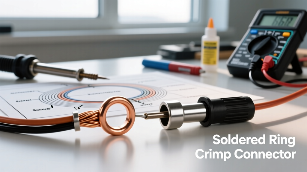
While soldering relies on thermal diffusion, crimping relies on cold flow and mechanical deformation. A crimp terminal is forcefully compressed around a wire using a precision die, squeezing out all oxygen and creating a gas-tight seal that prevents oxidation.
Head-to-Head Comparison Matrix
| Feature | Hand Soldering | Precision Crimping |
|---|---|---|
| Primary Bond Type | Metallurgical (Intermetallic Compound) | Mechanical (Gas-tight cold weld) |
| Tooling Cost (2026) | $110 - $250 (e.g., Pace ADS200) | $350 - $800 (e.g., TE Connectivity Pro-Crimper III) |
| Vibration Resistance | >Moderate (Brittle IMC can fracture)Exceptional (Strain relief built into terminal) | |
| Thermal Stress | High (Heat can damage nearby plastics/ICs) | None (Cold process) |
| Failure Mode | Cold joints, thermal pad lift, flux corrosion | Fretting corrosion, wire strand cut-off, pull-out |
| Best Application | PCB components, rigid wire-to-board | Automotive, aerospace, heavy-gauge power wiring |
The Verdict: If you are building a wire harness for an automotive ECU or an off-road vehicle, crimping is vastly superior due to its resistance to high-frequency vibration. Solder wicking into a stranded wire creates a rigid point that acts as a stress concentrator, eventually snapping the wire under vibration. However, for printed circuit board (PCB) terminations and surface mount technology (SMT), soldering remains the undisputed king.
Soldering vs. Wire Wrapping: The Cold-Weld Alternative
Before multi-layer PCBs became cheap and ubiquitous, wire wrapping was the backbone of aerospace and telecommunications prototyping. Wire wrapping involves tightly wrapping 24 AWG to 30 AWG solid wire around a square, sharp-edged copper post using a high-speed pneumatic or manual tool.
Why Wire Wrapping Still Matters
The sharp corners of the square post bite into the solid wire, displacing the copper oxide layer and creating a gas-tight cold weld. Historically governed by NASA STD 8739.3, a properly executed wire wrap joint actually boasts a higher tensile strength than the wire itself.
- Pros: Zero thermal damage to sensitive components; easily reworkable (unwrapped and re-wrapped); highly reliable in extreme thermal cycling.
- Cons: Limited to solid core wire; requires specialized wire-wrap posts; high labor intensity for complex modern digital circuits; unsuitable for high-frequency RF signals due to inductance of the wrapped loops.
Today, wire wrapping is largely relegated to legacy military repairs, specialized sensor prototyping, and high-reliability environments where thermal soldering might destroy a delicate thermistor or custom ASIC.
Soldering vs. Press-Fit (Compliant Pin) Technology
In modern backplane and high-density server manufacturing, press-fit technology has emerged as a major competitor to wave and reflow soldering. Press-fit pins feature a compliant, eye-of-the-needle geometry that deforms elastically when pushed into a plated through-hole (PTH) on a PCB.
The friction and radial force create a permanent, gas-tight electrical connection without a single drop of solder or application of heat. This eliminates the risk of thermal warping on thick, 20+ layer backplanes and prevents solder wicking into the board vias, which can cause internal short circuits. However, press-fit requires expensive, precision-machined CNC tooling and immense, evenly distributed insertion force, making it entirely impractical for DIYers or low-volume repair shops.
Modern Soldering Alloys: The 2026 Landscape
Understanding what is soldering also requires understanding the materials. The transition to lead-free soldering, mandated globally by the European Commission RoHS Directive, fundamentally changed the thermal requirements of electronics assembly.
Leaded (Sn63/Pb37) vs. Lead-Free (SAC305)
- Sn63/Pb37 (Eutectic): Melts at a sharp 183°C. It has a distinct liquid-to-solid transition with no plastic state, minimizing disturbed joints. Still permitted for aerospace, medical, and military exemptions where absolute long-term reliability (and avoidance of tin whiskers) is critical. Note that handling lead requires strict adherence to safety protocols outlined by the Occupational Safety and Health Administration (OSHA).
- SAC305 (Lead-Free): Melts between 217°C and 220°C. Requires higher iron tip temperatures (typically 320°C to 350°C). It exhibits a "plastic" or pasty state during cooling, meaning any movement during this phase will result in a grainy, fractured joint. SAC305 is also more prone to tin whisker growth—microscopic conductive crystals that can cause short circuits years after assembly.
Decision Framework: Which Method Should You Choose?
When designing a product or planning a repair in your workshop, use this rapid decision framework to select your termination method:
- Is it a PCB component (SMT or Through-Hole)? Choose Soldering. Neither crimping nor wire wrapping scales to modern 0402 or QFN surface-mount footprints.
- Is it a high-vibration wire harness (Automotive/Robotics)? Choose Crimping. Avoid soldering stranded wires that will flex repeatedly.
- Is it a high-density backplane or server connector? Choose Press-Fit to avoid thermal board warpage and flux residue.
- Are you prototyping with sensitive, heat-vulnerable discrete sensors? Consider Wire Wrapping or mechanical screw terminals to eliminate thermal shock.
Final Thoughts
Soldering is far more than just melting metal with a hot iron; it is a precise chemical diffusion process that forms the nervous system of modern electronics. While mechanical alternatives like crimping and wire wrapping offer distinct advantages in vibration resistance and thermal safety, soldering remains the most versatile, cost-effective, and universally applicable method for creating permanent electrical connections. Mastering the metallurgy of the IMC layer and understanding the limitations of your chosen alloy are the true marks of an expert builder in 2026.