
Decoding Professional Soldering Guidelines for DIYers
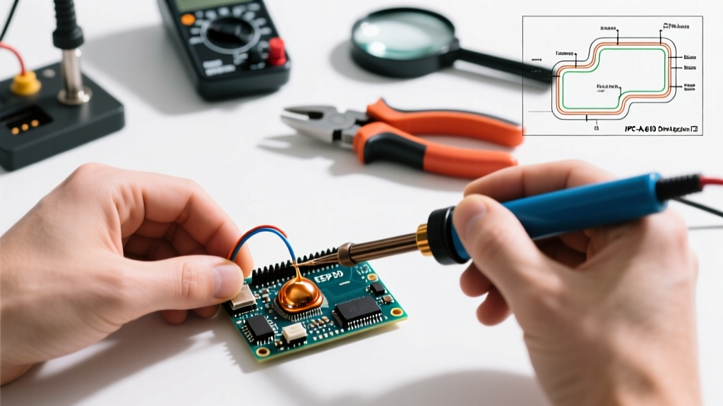
Soldering is fundamentally a metallurgical bonding process, not merely a mechanical glue. Whether you are assembling a custom ESP32 sensor node or repairing a vintage audio amplifier, adhering to established soldering guidelines is the difference between a reliable circuit and a latent failure waiting to happen. In the professional electronics manufacturing sector, the IPC-A-610 standard dictates acceptability for electronic assemblies. While DIYers and hobbyists are rarely held to Class 3 (High-Performance) aerospace requirements, aiming for Class 2 (Standard) ensures your projects survive thermal cycling, vibration, and long-term oxidation.
This comprehensive guide translates industrial-grade protocols into actionable, bench-level practices for 2026, covering thermal profiling, flux chemistry, and defect mitigation.
Thermal Profiling: Matching Alloys to Components
The most common violation of basic soldering guidelines is running an iron too hot to "melt the solder faster." Excessive heat degrades flux activity, delaminates PCB pads, and destroys sensitive silicon dies. Your iron's set temperature must be calibrated to the specific alloy's liquidus point plus a thermal delta for heat transfer efficiency.
Alloy Temperature Matrix
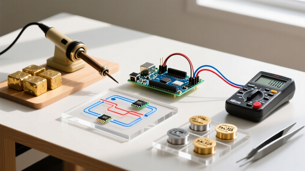
| Alloy Composition | Melting Point (Liquidus) | Recommended Iron Temp | Best Use Case |
|---|---|---|---|
| Sn63/Pb37 (Eutectic Leaded) | 183°C (361°F) | 300°C - 320°C | General through-hole, prototyping, vintage repair |
| SAC305 (Sn96.5/Ag3.0/Cu0.5) | 217°C (423°F) | 350°C - 380°C | Modern RoHS-compliant SMD, commercial production |
| Sn42/Bi57 (Bismuth Low-Temp) | 138°C (280°F) | 200°C - 220°C | Heat-sensitive components, step-soldering |
Expert Note: When using a high-thermal-mass ground plane, do not simply turn up the iron to 450°C. Instead, switch to a larger tip geometry (like a Hakko T18-D24 or JBC C245-764) to increase the surface area contact, which transfers BTUs far more efficiently than a needle tip at extreme temperatures.
The 2026 Equipment Baseline
Modern soldering stations utilize direct-drive cartridge tips where the heating element and thermocouple are integrated into the tip itself. This provides near-instantaneous thermal recovery. If you are still using a traditional ceramic heater with a separate tip sleeve (like the classic Hakko FX-888D), you are operating with a 15-year-old thermal lag profile. For serious bench work in 2026, consider upgrading to cartridge-based systems:
- Budget/Travel: Pine64 Pinecil V2 (~$26). Runs on PD 3.0, supports RISC-V custom firmware, and uses T12-compatible tips.
- Prosumer: Miniware MHP50 (~$130). Excellent for localized PCB preheating and SMD rework.
- Professional: JBC CD-2BQE (~$450). Unmatched thermal recovery for heavy ground-plane soldering using C245 cartridges.
Flux Chemistry: The Unsung Hero of Metallurgical Bonds
Flux removes metal oxides and prevents re-oxidation during the heating phase. Without it, surface tension prevents the solder from wetting the pad. Choosing the right flux is a critical pillar of professional soldering guidelines.
Flux Types and Applications
- Rosin Mildly Activated (RMA): The traditional standard (e.g., Kester 186). Excellent wetting, but leaves a sticky, mildly corrosive residue that must be cleaned with 99% isopropyl alcohol (IPA) or a dedicated saponifier.
- No-Clean (NC): Formulated with synthetic resins (e.g., Amtech NC-559-V2-TF). Leaves a clear, hard, non-conductive residue. Ideal for SMD rework where cleaning under tight-pitch QFN chips is impossible. Warning: No-clean fluxes can become conductive if subjected to high humidity before fully curing, or if mixed with incompatible chemistries.
- Water-Soluble (OA): Highly active organic acids. Used for heavily oxidized boards or difficult-to-solder metals like nickel. Must be thoroughly rinsed with distilled water immediately after soldering to prevent severe galvanic corrosion.
Pro-Tip: Never rely on the flux core inside your solder wire for SMD rework or drag soldering. Always apply supplemental liquid or tacky flux directly to the pads before introducing heat. The core flux boils off in milliseconds; supplemental flux sustains the chemical reaction throughout the 2-3 second dwell time.
Execution Protocols: Through-Hole vs. Surface Mount
Proper technique minimizes thermal stress on components. The NASA Electronic Parts and Packaging (NEPP) Program workmanship manuals emphasize a specific sequence for heat application to ensure optimal wetting without component damage.
Through-Hole (TH) Sequence
- Prep: Ensure the lead is clean and properly formed. Apply a tiny amount of flux to the barrel if the board is older than 6 months.
- Heat: Touch the iron tip simultaneously to the component lead and the inside edge of the plated through-hole (PTH) pad. Dwell for 1 second.
- Feed: Introduce the solder wire to the pad and lead, not the iron tip. Capillary action will draw the solder into the barrel.
Withdraw: Remove the solder wire first, then the iron, sweeping slightly upward to create a smooth concave fillet.
Surface Mount (SMD) Sequence for Passives (0603/0805)
- Tin One Pad: Apply a small amount of solder to one PCB pad.
- Anchor: Re-melt the tinned pad with tweezers holding the component. Slide the component into the molten pool and remove heat. Let it solidify for 2 seconds.
- Solder Second Pad: Apply flux to the second pad, touch the iron to the pad and component terminal, and feed a micro-amount of solder.
- Dress the First Pad: Briefly reflow the first pad with a touch of fresh flux to ensure matching fillet geometry.
Defect Diagnostics and Corrective Actions
Even experienced engineers encounter anomalies. Recognizing the visual signatures of poor wetting is essential for applying the correct corrective action.
| Defect | Visual Signature | Root Cause | Corrective Action |
|---|---|---|---|
| Cold Joint | Dull, grainy, convex blob | Movement during solidification or insufficient heat | Apply fresh RMA flux, reheat to liquidus + 30°C for 3 seconds, hold perfectly still. |
| Tombstoning | Component stands vertically on one end | Uneven heating of pads; one pad reaches liquidus first | Use a smaller tip to restrict heat spread, or preheat the PCB to 100°C on a hotplate. |
| Solder Bridging | Short circuit between adjacent IC pins | Excessive solder volume, depleted flux, or dirty tip | Flood with no-clean liquid flux, drag a flux-soaked Goot Wick CP-2060 braid across the pins. |
| Non-Wetting | Solder balls up and rolls off the pad | Severe pad oxidation or silicone conformal coating residue | Clean pad with fiberglass scratch pen, apply OA water-soluble flux, re-tin. |
Tip Longevity and Thermal Shock Prevention
A common violation of modern soldering guidelines is the use of a wet cellulose sponge to clean lead-free soldering tips. Lead-free alloys (like SAC305) require higher operating temperatures. Plunging a 380°C iron tip into a room-temperature wet sponge causes instantaneous thermal shock. This micro-cracks the iron plating on the tip, allowing the molten solder to dissolve the underlying copper core, destroying the tip in weeks.
The 2026 Maintenance Standard:
- Use a dry brass wire sponge (e.g., Hakko 599B) for routine cleaning. It removes oxidation without dropping the tip temperature.
- Always "tin and bin"—leave a thick coat of fresh solder on the tip before powering down the station to act as a sacrificial oxidation barrier.
- Never use abrasive sandpaper or files on modern iron-plated tips. Once the plating is breached, the tip is e-waste.
For deeper insights into tip degradation and thermal management, refer to the technical bulletins provided by Hakko Technical Support, which detail the exact metallurgical failure modes of improperly maintained cartridge tips.
Final Thoughts on Bench Discipline
Mastering soldering guidelines is about building muscle memory rooted in physics and chemistry. By respecting the liquidus points of your alloys, leveraging the correct flux chemistry for the environment, and maintaining your thermal transfer tools, you will produce joints that are not only visually pristine but electrically and mechanically bulletproof. Invest in a good magnification lamp, keep your brass sponge clean, and let the flux do the heavy lifting.