
The Physics of the Bond: Metallurgical vs. Mechanical
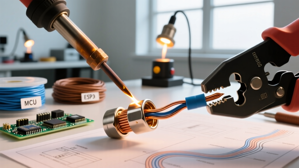
When terminating wires to connectors in aerospace, automotive, or consumer electronics, engineers face a fundamental fork in the road: connector soldering or precision crimping. While both methods aim to establish a low-resistance electrical path and robust mechanical anchor, the physics governing their success are entirely different. Soldering relies on a metallurgical bond where a molten filler metal (typically a tin-lead or SAC305 alloy) wets the copper strands and the terminal surface, forming intermetallic compounds. Crimping, conversely, is a cold-welding process. It uses extreme localized mechanical pressure to plastically deform the terminal and wire, breaking through surface oxides to create a gas-tight, solid-state mechanical bond.
Choosing between the two is rarely a matter of personal preference; it is dictated by environmental stressors, production volume, and stringent industry standards like IPC/WHMA-A-620. This guide dissects the technical realities, failure modes, and economic factors of both termination methods to help you engineer the most reliable wire harness for your specific application.
Deep Dive: Connector Soldering Techniques
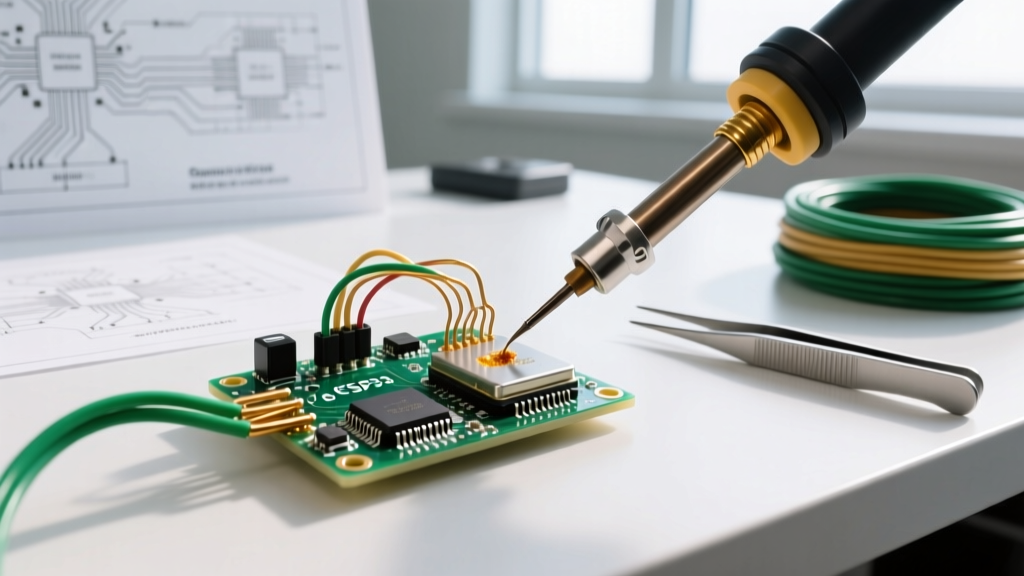
Connector soldering is predominantly used for solder-cup terminals (such as D-subminiature, XLR audio connectors, and MIL-SPEC circular connectors) and direct-to-PCB header pins. The process requires precise thermal management to ensure the solder flows via capillary action into the wire strands without compromising the connector's plastic dielectric housing.
Best Practices and Tooling
- Preparation: Strip the wire precisely to the depth of the solder cup. Pre-tin both the wire strands and the inside of the solder cup using a high-quality flux (e.g., Amtech NC-559 no-clean flux) to prevent cold joints.
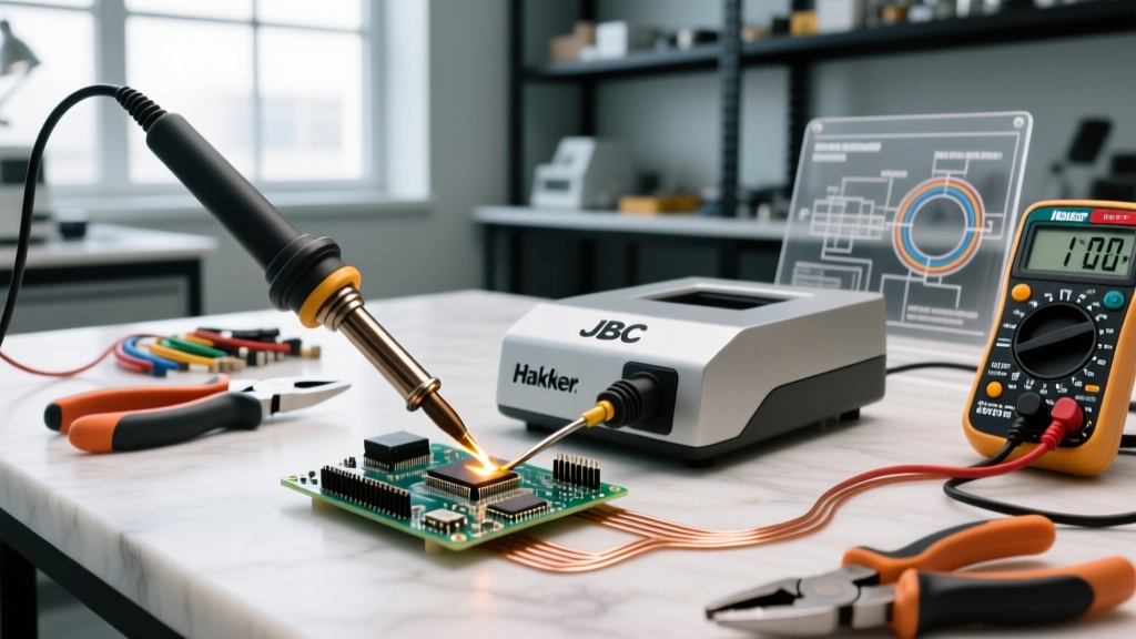
- Thermal Control: Use a temperature-controlled station like the Weller WE1010NA or JBC CD-2BQE. For leaded Sn63/Pb37 solder, set the tip to 320°C. For lead-free SAC305, increase to 360°C to compensate for the higher melting point and poorer wetting characteristics.
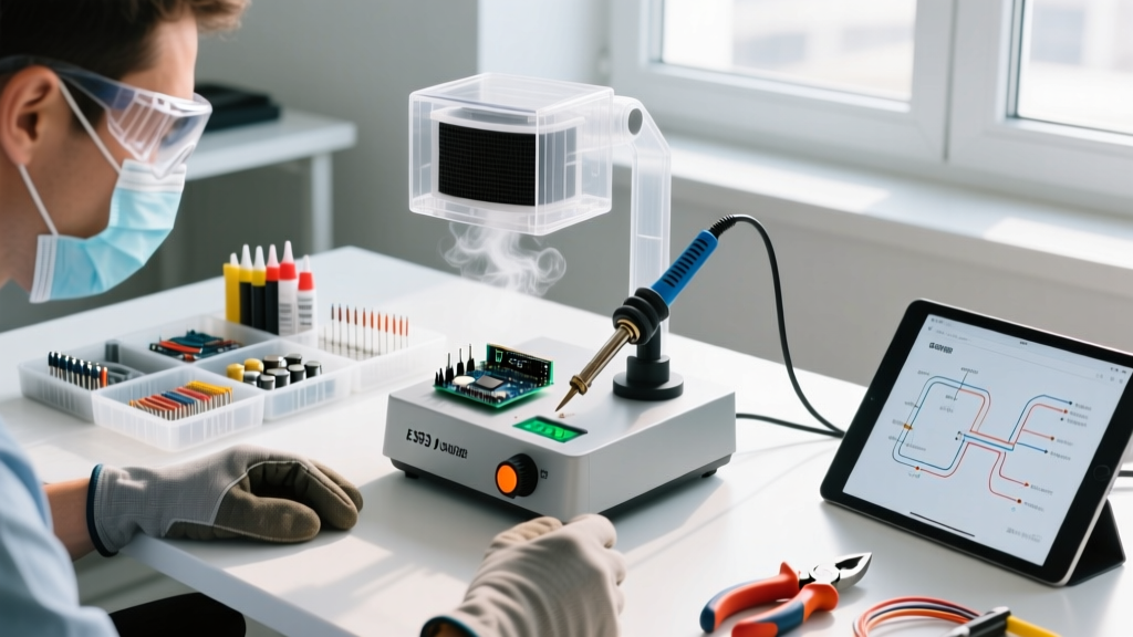
- Heat Sinking: When soldering near sensitive plastic housings or RF coaxial connectors, use thermal tweezers or a hemostat clamped between the solder cup and the sensitive component to act as a heat sink, preventing dielectric melt.
- Strain Relief: Soldered connections are rigid. Always slide a piece of dual-wall adhesive-lined heat shrink tubing (e.g., 3M MDT or Raychem) over the joint. When heated, the inner meltable adhesive seals the connection against moisture and provides critical mechanical strain relief.
Deep Dive: Precision Crimping Mechanics
Crimping is the undisputed standard for high-reliability wire-to-wire and wire-to-board connections, dominating the automotive (Molex MX150), aerospace (TE Connectivity DEUTSCH), and industrial sectors. A proper crimp is not merely 'squishing' metal; it is a highly engineered deformation.
The Anatomy of a Perfect Crimp
According to NASA Workmanship Standard NASA-STD-8739.3, a flawless open-barrel or closed-barrel crimp must exhibit specific geometric features:
- Conductor Brush: The wire strands must protrude slightly (0.5mm to 1mm) past the front of the conductor crimp barrel, proving the wire was fully inserted before deformation.
- Bellmouth: The rear edge of the conductor barrel must flare outward slightly. This prevents the sharp edge of the terminal from shearing the copper strands during vibration.
- Insulation Crimp: The secondary crimp barrel should securely grip the wire's insulation without piercing it, acting as the primary strain relief to protect the conductor crimp from mechanical pull.
To achieve this, you must use matched, ratcheting tooling. A Molex 63819-series hand crimper or a TE Connectivity CERTI-CRIMP tool ensures the cycle only completes when the exact predetermined compression force is reached, eliminating human error.
Head-to-Head Comparison Matrix
| Feature | Connector Soldering | Precision Crimping |
|---|---|---|
| Bond Type | Metallurgical (Intermetallic) | Mechanical (Cold-weld, Gas-tight) |
| Vibration Resistance | Moderate (Prone to fatigue cracking) | Excellent (Strands flex independently) |
| Thermal Cycling | Poor (Solder can creep or crack) | Excellent (Metals expand together) |
| Tooling Cost (2026) | Low to Moderate ($100 - $550) | High ($350 - $2,500+ per die set) |
| Production Speed | Slow (Heat, cool, inspect, shrink) | Fast (Sub-second cycle with auto tools) |
| Reworkability | High (Desolder and repeat) | Low (Terminal is destroyed upon removal) |
Critical Failure Modes: Where Terminations Fail
Understanding how connections fail in the field is crucial for selecting the right method. Both techniques have distinct edge cases and failure vectors.
Soldering Failure Vectors
The most insidious failure in connector soldering is solder wicking. If too much heat or flux is applied, molten solder wicks up into the flexible stranded wire via capillary action. This creates a rigid, brittle section of wire right at the exit of the solder cup. Under continuous vibration (such as in automotive or drone applications), the wire experiences extreme stress concentration at the exact boundary where the flexible wire meets the rigid, solder-wicked section. This inevitably leads to a fatigue fracture and an open circuit. Additionally, excessive heat can degrade the plastic insulator of the connector, leading to short circuits or loss of mating retention.
Crimping Failure Vectors
Crimping failures are almost entirely the result of incorrect tooling or operator error. Under-crimping (using a die that is too large or a worn-out tool) leaves voids between the strands, resulting in high electrical resistance, localized heating, and eventual pull-out. Over-crimping (using a die that is too small) acts like a pair of scissors, cutting or deeply scoring the outer copper strands, drastically reducing the wire's tensile strength and current-carrying capacity. Using a non-ratcheting crimper (like a cheap pair of pliers-style crimpers) guarantees inconsistent compression, which fails to achieve the necessary gas-tight seal, allowing oxygen to penetrate and oxidize the copper over time.
Cost and Tooling Economics in 2026
When budgeting for a production run or a high-end DIY project, the economics of the two methods diverge sharply. A high-quality, temperature-controlled soldering setup is relatively inexpensive. A Weller WE1010NA station costs around $115, and bulk rolls of Kester 245 flux-core solder and adhesive heat shrink add perhaps $40 to the bill. The primary cost in soldering is labor time.
Crimping demands a massive upfront capital expenditure. Authentic, OEM-certified ratcheting hand crimpers from Molex or TE Connectivity routinely cost between $380 and $450 per terminal family. If your harness uses three different terminal sizes (e.g., 22 AWG, 18 AWG, and 14 AWG), you are looking at over $1,200 just for hand tooling. However, once the tooling is acquired, the per-unit termination cost plummets. A pneumatic or automatic crimping machine can terminate thousands of wires per hour, making crimping the only economically viable choice for high-volume manufacturing.
What the Standards Say: IPC and NASA Guidelines
For mission-critical applications, industry standards dictate the termination method. The NASA-STD-8739.4 standard for soldering strictly limits the use of solder on wires that will be subjected to high-flex or high-vibration environments, explicitly warning against solder wicking. Conversely, NASA-STD-8739.3 mandates crimping for almost all aerospace wire harness terminations due to its superior resistance to thermal shock and mechanical vibration.
Expert Insight: In commercial aviation and military aerospace, solder is largely banned for wire-to-connector terminations. It is reserved almost exclusively for solder-cup PCB mounting features or RF coaxial center pins where mechanical flex is zero and high-frequency signal integrity is paramount.
The Final Verdict: Which Method Should You Choose?
There is no universal 'best' method; there is only the right method for the environment.
- Choose Connector Soldering if: You are working with solder-cup connectors (D-sub, circular MIL-SPEC, audio XLR), repairing legacy equipment, prototyping low-volume harnesses, or terminating RF coaxial cables where signal impedance and metallurgical continuity are critical.
- Choose Precision Crimping if: You are building wire harnesses for automotive, marine, aerospace, or robotics applications. If the wire will experience vibration, thermal cycling, or mechanical pulling, a properly executed cold-weld crimp using OEM ratcheting tooling is vastly superior and significantly more reliable over the product's lifecycle.
By matching the termination physics to your environmental stressors, you ensure your electrical assemblies survive the rigors of the real world, avoiding costly field failures and warranty claims.