
The Hidden Safety Hazards of a Soldering Dry Joint
In the electronics assembly and repair community, a soldering dry joint (often referred to as a cold solder joint) is typically discussed as a reliability nuisance—a connection that might cause a device to malfunction or intermittently fail. However, from a safety engineering perspective, a dry joint is a severe hazard. When a solder connection fails to form a proper intermetallic compound (IMC) layer, it introduces localized high electrical resistance. In power electronics, automotive systems, or high-voltage applications, this resistance transforms a simple mechanical defect into a potential ignition source for electrical fires.
As we move through 2026, the industry-wide mandate for lead-free alloys like SAC305 (Sn96.5/Ag3.0/Cu0.5) has made thermal management more critical than ever. Lead-free solders require higher reflow temperatures (typically 217°C to 225°C melting point, requiring iron tips set between 340°C and 380°C). This narrower thermal window increases the likelihood of creating a soldering dry joint if the operator lacks precise temperature control or proper flux chemistry. This guide details the physics of dry joint failures, outlines strict safety best practices for prevention, and provides a step-by-step protocol for safe remediation.
The Physics of Failure: Why Dry Joints Cause Thermal Runaway
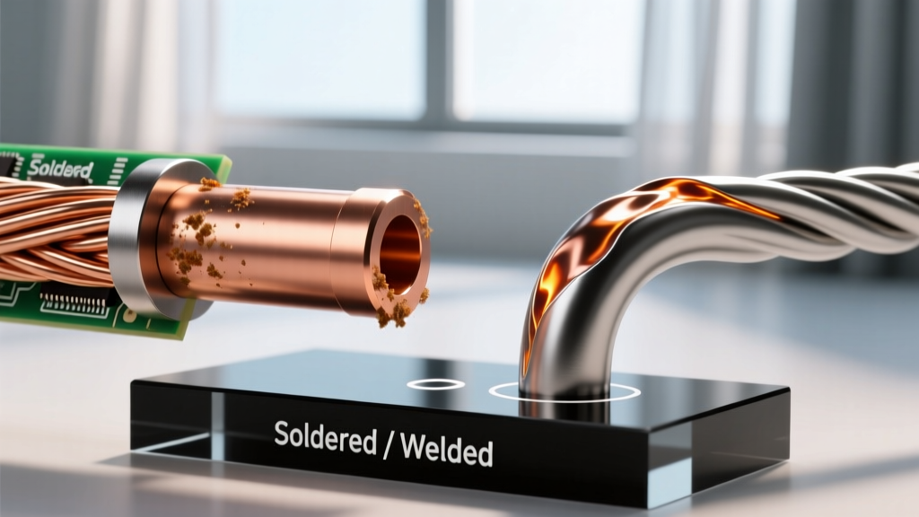
To understand the safety risk, we must look at the electrical physics of a compromised joint. An ideal solder joint forms a continuous, low-resistance IMC layer (typically 1 to 3 micrometers thick) between the copper pad and the component lead. A soldering dry joint occurs when the solder merely sits on top of the pad or lead without metallurgical wetting, often separated by a microscopic layer of copper oxide or burned flux residue.
The Joule Heating Effect
This lack of wetting creates a high-resistance point in the circuit. According to Joule's First Law, the heat generated by an electrical conductor is proportional to the square of the current multiplied by the resistance (P = I²R).
- Ideal Joint Resistance: ~0.001 Ω
- Dry Joint Resistance: Can range from 0.1 Ω to several ohms depending on the oxide layer and micro-cracking.
If a 10-ampere motor control circuit passes through a dry joint with just 0.5 Ω of resistance, that single microscopic joint will dissipate 50 watts of heat (10² x 0.5 = 50W). This localized thermal spike will rapidly exceed the glass transition temperature (Tg) of standard FR-4 PCB material (typically 130°C to 170°C). The resulting thermal runaway causes the PCB substrate to delaminate, outgas toxic brominated flame retardants, and potentially ignite surrounding components or conformal coatings.
Visual and Electrical Identification Matrix
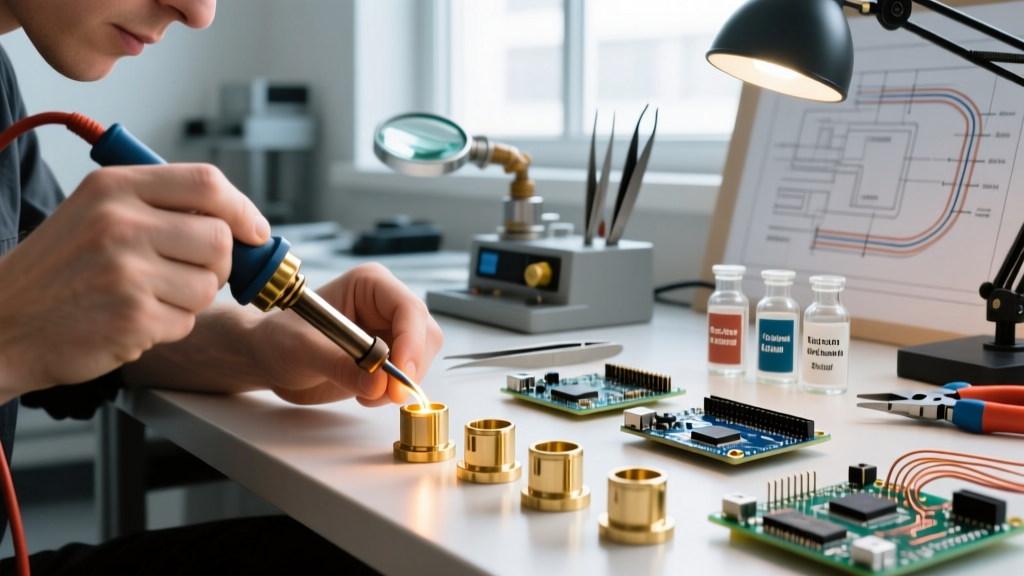
Identifying a soldering dry joint before it becomes a safety hazard requires trained visual inspection, often aided by a 10x to 30x stereomicroscope. The table below contrasts an acceptable joint with a hazardous dry joint based on IPC-A-610 Standard criteria.
| Inspection Characteristic | Ideal Solder Joint (Safe) | Soldering Dry Joint (Hazardous) |
|---|---|---|
| Surface Appearance | Smooth, shiny, and reflective (for leaded); smooth but slightly matte/dull (for lead-free SAC alloys). | Distinctly grainy, rough, excessively dull, or crystalline. May show visible ridges or a 'frosty' texture. |
| Wetting & Fillet Shape | Concave fillet that flows smoothly from the component lead to the pad edge, demonstrating excellent capillary action. | Convex, balled-up, or bulbous shape. The solder appears to sit on the pad like a water droplet on a waxed car (dewetting). |
| Mechanical Integrity | Rigid and solid. The component lead cannot be moved independently of the PCB pad. | Brittle. Often features a visible microscopic ring of separation (crater) around the base of the lead. |
| Thermal Signature | Remains at ambient or expected operational temperature under load. | Exhibits localized hot spots detectable via thermal imaging cameras (e.g., FLIR E8-XT) when under electrical load. |
Safety Best Practices for Prevention
Preventing a soldering dry joint is fundamentally about thermal management and chemical preparation. Relying on guesswork or outdated equipment is a severe safety liability in professional environments.
1. Precision Thermal Profiling
Modern digital soldering stations use closed-loop thermal sensors to maintain tip temperature. For lead-free SAC305 assemblies, set your station (such as the Hakko FX-888D or Weller WE1010NA, both retailing around $115–$130 in 2026) to 350°C–360°C.
Expert Insight: Never compensate for a large ground plane by turning the iron up to 400°C+. Excessive heat instantly burns the rosin core in your solder wire, leaving the joint unprotected from oxidation and guaranteeing a dry joint. Instead, use a larger tip geometry (like a bevel or wide chisel) to increase thermal mass transfer without spiking the temperature.
2. Aggressive Flux Management
Flux is the chemical engine that prevents dry joints by dissolving copper oxides. The rosin core inside standard solder wire is rarely sufficient for rework or through-hole components with heavy thermal sinks. Always supplement with an external, high-activity flux.
- For Leaded (Sn63/Pb37): Use a mildly activated rosin flux like Kester 186. It provides excellent wetting without leaving highly corrosive residues.
- For Lead-Free (SAC305): Use a no-clean, high-thermal-stability gel flux like Amtech NC-559-V2-TF. Lead-free solders require longer dwell times; standard liquid fluxes will boil off before the solder reaches its 217°C liquidus point.
3. Strict Dwell Time Limits
According to NASA NEPP Soldering Techniques and general aerospace workmanship standards, the iron-to-joint contact time should not exceed 3 to 4 seconds. Prolonged heating boils away the flux, oxidizes the molten solder pool, and degrades the copper pad's adhesion to the fiberglass substrate, all of which are primary catalysts for a soldering dry joint.
Step-by-Step Safe Repair Protocol
If a dry joint is identified during QA or field maintenance, it must be repaired using a controlled methodology to avoid compounding the safety hazard.
- Isolate and Prep: Remove all power. Clean the area with 99% isopropyl alcohol (IPA) to remove surface contaminants that could be driven into the joint during reflow.
- Apply External Flux: Generously apply Kester 186 or Amtech NC-559 gel flux to the compromised joint. Do not skip this step; adding fresh solder to a dry joint without fresh flux will only create a larger, equally unreliable dry joint.
- Select the Correct Tip: Install a clean, properly tinned chisel tip (e.g., Hakko T18-D12). A conical tip will fail to transfer the necessary thermal mass to break the oxide barrier.
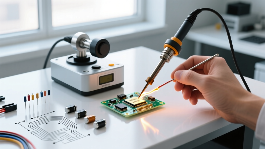
- Reflow and Add Solder: Apply the iron to both the pad and the lead simultaneously. Once the existing solder flashes into a liquid state (usually 1.5 to 2 seconds), feed a small amount of fresh, flux-cored solder wire into the joint to replenish the alloy and introduce fresh reducing agents.
- Hold Still: Remove the iron and the solder wire. Crucial: Do not move the component or blow on the joint while it cools. Disturbing a cooling lead-free joint causes micro-fractures in the crystalline structure, instantly recreating a dry joint.
- Clean and Inspect: Once cooled, clean the residue with a dedicated solvent like Chemtronics Flux-Off. Inspect under 10x magnification to ensure a smooth, concave fillet with proper wetting angles.
Frequently Asked Questions (FAQ)
Can I just melt the existing solder and let it cool to fix a dry joint?
No. A soldering dry joint is characterized by an oxide barrier between the solder and the copper. Simply reheating the solder without introducing fresh chemical flux will not break this barrier. The solder will remain balled up and unwetted once it cools. Fresh flux is mandatory for a safe repair.
Does a dry joint always cause an immediate failure?
Rarely. The most dangerous aspect of a dry joint is its latency. A joint may pass initial continuity testing but fail weeks later due to thermal expansion and contraction cycles (CTE mismatch) during normal operation. This mechanical stress widens the microscopic cracks in the poor IMC layer, gradually increasing resistance until thermal runaway occurs.
Are lead-free dry joints more dangerous than leaded ones?
From a mechanical standpoint, yes. Lead-free alloys like SAC305 are inherently more brittle and prone to tin whisker growth and micro-cracking under vibration. A lead-free dry joint is highly susceptible to catastrophic mechanical fracture, which can cause arcing in high-voltage circuits, posing a severe shock and fire hazard.
Conclusion
Treating a soldering dry joint as a mere cosmetic defect is a critical safety oversight. By understanding the thermal dynamics of IMC formation, utilizing precision temperature-controlled equipment, and adhering to strict flux and dwell-time protocols, technicians can eliminate the hidden fire and shock hazards associated with poor solder wetting. Always validate your repairs against IPC-A-610 standards to ensure the long-term safety and reliability of your electronic assemblies.