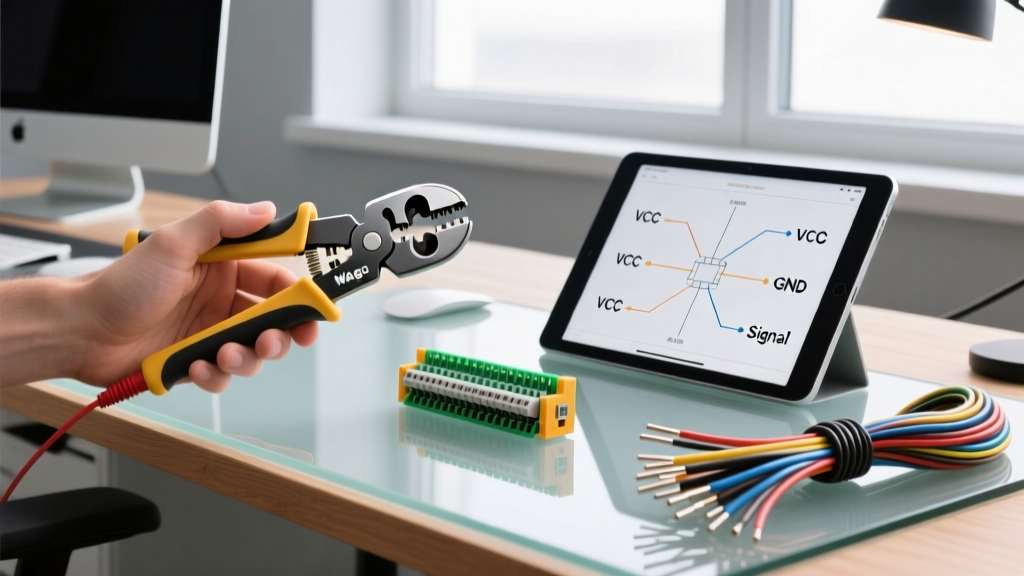

The Case Against Soldering in High-Stress Environments
While soldering remains the gold standard for printed1-board assembly and static electronics, it is often the wrong choice for wire-to-wire or wire-to-chassis connections in dynamic environments. When learning the best practices for connecting wires without soldering, engineers and technicians must recognize the mechanical limitations of tin-lead and lead-free solder joints. Solder wicking can create a stiff transition point just outside the insulation, which becomes a prime failure node under continuous vibration (a phenomenon well-documented in MIL-STD-810 vibration testing). Furthermore, field repairs, high-current automotive harnesses, and industrial control panels demand connection methods that are verifiable, reworkable, and compliant with modern electrical codes.
This decision framework evaluates the top solderless connection methodologies available in 2026, breaking down exact tooling costs, mechanical specifications, and failure modes to help you complex wiring topologies.
The Wire Connection Decision Matrix
Use the following matrix to quickly identify the optimal solderless method based on your specific environmental and electrical constraints.
| Connection Method | Optimal AWG Range | Vibration Resistance | Initial Tool Cost | Primary Use Case |
|---|---|---|---|---|
| Lever-Nut (Spring Clamp) | 24 - 12 AWG | High | $0 (Toolless) | Junction boxes, lighting, field repair |
| Ferrule / Pin Crimp | 28 - 8 AWG | Very High | $45 - $120 | Terminal blocks, PCB headers, harnesses |
| Screw Terminal Block | 22 - 2 AWG | Moderate to High | $5 - $15 (Torque driver) | DIN rail panels, industrial I/O |
| IDC (Insulation Displacement) | 28 - 22 AWG | Low | $20 - $40 | Telecom, low-voltage data, ribbon cables |
| Twist-On (Wire Nuts) | 18 - 10 AWG | Low | $0 (Toolless) | Residential AC mains, static junctions |
Method 1: Lever-Nut Connectors (Spring Clamp Technology)
Spring-clamp technology has largely rendered traditional twist-on wire nuts obsolete in professional environments. The market leader, WAGO, revolutionized this space with their lever-nut designs, which utilize a clamping spring mechanism to maintain constant, temperature-independent pressure on the conductor.
WAGO 221 Series Deep Dive
- Model Focus: WAGO 221-413 (3-conductor lever nut).
- Specifications: Accepts 24-12 AWG (0.2 to 4.0 mm²), rated for 32A and 400V. Maximum operating temperature of 105°C.
- Installation Metric: Requires exactly 11mm (7/16 inch) of insulation stripping. The built-in strip gauge on the lever mold eliminates guesswork.
- Cost Analysis: Approximately $0.35 to $0.45 per unit in bulk trays, making them highly economical for mass production or large-scale commercial fit-outs.
Failure Mode Warning: The most common failure with lever nuts occurs when stranded wire is not fully inserted before closing the lever, or when the lever is not depressed until it audibly clicks. This results in a high-resistance connection that can arc and melt the polycarbonate housing under continuous 20A+ loads.
Method 2: Precision Crimping (Ferrules and Terminals)
Crimping relies on cold-welding the terminal barrel to the wire strands through precise mechanical deformation. When executed to IPC/WHMA-A-620 standards, a crimped connection actually outperforms solder in tensile strength and conductivity because it avoids the formation of brittle intermetallic compounds.
Tooling and Ferrule Standards
For terminating stranded wire into screw terminals or PCB headers, wire ferrules (sleeves) are mandatory in European and high-end industrial applications to prevent strand splaying. Ferrules should comply with DIN 46228 dimensional standards.
- The Tool: Avoid cheap, non-ratcheting pliers. Invest in a ratcheting ferrule crimper like the IWISS IWS-3220M (typically $45-$65). The ratchet mechanism ensures the crimp cycle is only released once the exact deformation pressure is achieved, preventing under-crimping.
- The Wire Prep: Strip the wire to match the ferrule pin length (usually 8mm to 12mm). Do not tin the wire with solder before crimping; solder creeps under pressure, leading to a loose connection over time.
- The Crimp: The insulation sleeve must be flush with the wire jacket, and the wire strands must be visible just past the metal tube (the 'bellmouth' effect is less critical for ferrules than for open-barrel terminals, but strand visibility is mandatory for IPC acceptance).
Method 3: Screw Terminal Blocks and DIN Rail Systems
For industrial control panels, modular screw terminal blocks (such as those from Phoenix Contact or Weidmüller) offer unparalleled flexibility. However, connecting wires without soldering into screw terminals requires strict adherence to torque specifications.
When using a 2.5mm² (12 AWG) wire in a standard M3 screw terminal, the manufacturer typically specifies a tightening torque of 0.6 Nm to 0.8 Nm. Under-torquing leads to thermal cycling loosening the screw (due to differing coefficients of thermal expansion between the copper wire and steel screw). Over-torquing strips the block threads or shears the copper strands, reducing the cross-sectional area and creating a hot spot.
Pro-Tip: Always use a crimped ferrule on stranded wire before inserting it into a screw terminal. Directly clamping a screw onto bare stranded wire will sever the outer strands and severely degrade the connection's current-carrying capacity.
Method 4: Insulation Displacement Connectors (IDC)
IDC technology forces a sharp, U-shaped metal contact through the wire insulation to bite into the copper conductor. This is heavily utilized in telecommunications, Ethernet punch-down blocks (like BIX or Krone), and ribbon cables.
- Best For: Low-voltage, low-current signal routing (typically under 2A).
- Tooling: Requires a specific impact tool (e.g., a 110 or 66 punch-down tool) calibrated to the correct wire gauge to ensure the insulation is cleanly sheared and the wire is seated at the bottom of the slot.
- Limitation: IDCs are highly susceptible to corrosion in humid environments unless specifically sealed, and they cannot handle the thermal loads of AC mains power.
Compliance, Safety, and Edge Cases
When designing or repairing electrical systems, the National Electrical Code (NFPA 70 / NEC) strictly governs how conductors are spliced and terminated. Article 110.14 requires that termination means be identified for the specific conductor material (copper vs. aluminum) and that connections rely on listed equipment.
Code Compliance Alert: You cannot legally use a WAGO lever nut or a standard wire nut to splice wires inside a wall cavity unless the connector is UL-listed (e.g., UL 486A/486B) and housed within an approved, accessible junction box. 'In-wall' hidden splices using solderless connectors are a major fire hazard and a direct code violation.
High-Vibration Edge Cases
If your project involves automotive engine bays, aerospace panels, or heavy machinery, standard lever nuts and twist-on connectors will eventually fail due to fretting corrosion. In these scenarios, you must use ratcheting crimp terminals with heat-shrink adhesive seals (e.g., Molex Perma-Seal or TE Connectivity PIDG series). The hot-melt adhesive inside the heat shrink provides environmental sealing and immense strain relief, achieving pull-out forces exceeding 150 lbs on 12 AWG wire.
Summary Checklist for Engineers and Makers
- For quick, toolless AC mains splices in junction boxes: Use WAGO 221 Lever Nuts. Ensure 11mm strip length.
- For terminating stranded wire into PCB headers or terminal blocks: Use DIN 46228 ferrules with a ratcheting crimper.
- For automotive or high-vibration DC wiring: Use adhesive-lined heat-shrink crimp terminals.
- For industrial control panel modularity: Use DIN-rail terminal blocks with properly torqued M3/M4 screws and ferruled wires.
- Never: Solder a wire before crimping it, or clamp a screw terminal directly onto bare stranded wire without a ferrule.