
The Hidden Challenge of BGA Soldering
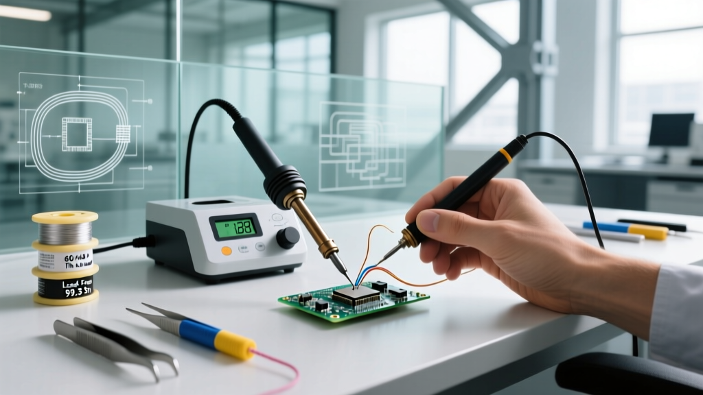
Ball Grid Array (BGA) components represent the final boss of PCB assembly and rework. Unlike QFP or SOIC packages, BGA solder joints are completely hidden beneath the component body, relying on a matrix of microscopic solder spheres to bridge the silicon substrate to the FR4 board. As of 2026, with the proliferation of high-density AI accelerators and 5G RF modules, BGA soldering has moved from high-volume manufacturing floors into advanced prototyping labs and repair benches.
The fundamental challenge of BGA soldering is thermal management. You are attempting to uniformly heat a complex assembly with mismatched Coefficients of Thermal Expansion (CTE). The silicon die expands at roughly 2.6 ppm/°C, while the FR4 PCB expands at 14-18 ppm/°C. If the thermal gradient across the package is too steep, dynamic warpage occurs, leading to catastrophic failure modes like Head-in-Pillow (HiP) or pad cratering. To mitigate this, engineers must choose the correct rework methodology. Below, we compare the three dominant BGA soldering methods: Hot Air (Convection), Infrared (Radiation), and Vapor Phase (Condensation).
Method 1: Hot Air Rework Stations (Convection)
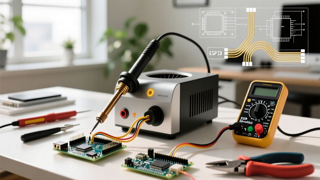
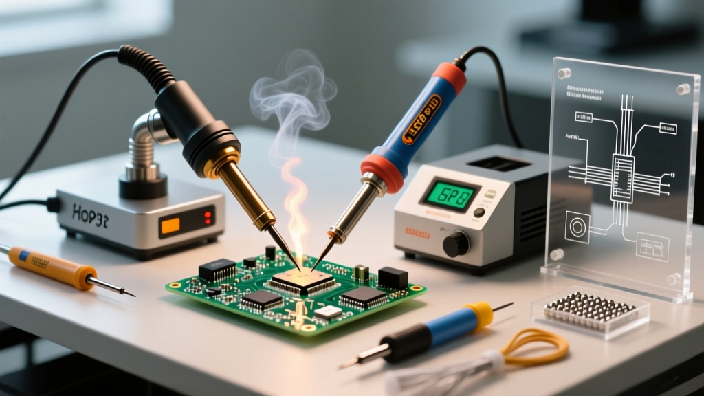
Hot air rework relies on forced convection. Heated nitrogen or ambient air is pushed through a specialized nozzle that matches the footprint of the BGA package. This is the most common method in DIY and mid-tier professional labs due to its versatility and lower entry cost.
Equipment and Economics
Entry-level stations like the Quick 861DW (approximately $250) can handle smaller BGAs (up to 15x15mm) if paired with a high-quality bottom preheater. For larger, multi-layer boards with high thermal mass, professional stations like the Hakko FR-830 (approximately $1,300) or the Weller WRS 3000 are required. These systems feature closed-loop thermocouple feedback and integrated IR bottom preheaters to keep the PCB core at 120°C, reducing the delta-T (temperature difference) between the top and bottom of the board.
The Shadowing and Airflow Dilemma
The primary drawback of hot air is airflow disruption. High-velocity air (often 30-50 L/min) can easily blow away adjacent 0201 or 0402 passive components. Furthermore, hot air suffers from the 'shadowing effect'—tall components adjacent to the BGA block the airflow, creating cold spots that result in incomplete reflow on the shadowed side of the BGA matrix.
Pro-Tip: When using hot air for BGA rework, always use a Kapton tape and aluminum foil shield to protect surrounding components, and reduce airflow to the minimum required to maintain temperature (typically 15-20 L/min for large BGAs) to prevent component displacement.
Method 2: Infrared (IR) Rework Stations (Radiation)
Infrared rework stations use electromagnetic radiation to heat the component. Modern IR stations utilize a mix of short-wave and long-wave IR emitters. Short-wave IR penetrates deeper and heats the internal silicon die, while long-wave IR heats the surface and the solder joints.
Equipment and Economics
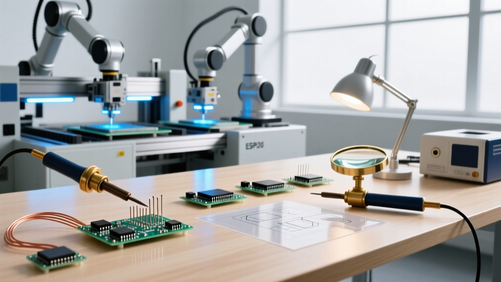
As of 2026, semi-automatic IR stations like the Zhuomao ZM-R5822 (approximately $1,600) dominate the prosumer and independent repair market. High-end automated systems from Finetech or Ersa can exceed $30,000, featuring optical split-vision alignment and automated profile execution.
The Color and Mass Absorption Problem
IR heating is highly dependent on the surface emissivity and absorptivity of the materials. Dark-colored components absorb IR energy rapidly, while light-colored or reflective surfaces (like metal RF shields) bounce it away. This can lead to severe thermal imbalances. Additionally, IR is strictly line-of-sight; any tall capacitor or connector next to the BGA will cast a literal thermal shadow, leaving the solder balls beneath the shadow in a solid state while the rest of the array melts.
Method 3: Vapor Phase Soldering (Condensation)
While primarily a mass-production tool, vapor phase technology is increasingly used in high-reliability prototyping (aerospace, medical). The PCB is lowered into a chamber containing a boiling inert fluid (like Galden). The vapor condenses on the cooler PCB, transferring latent heat with absolute uniformity until the entire assembly reaches the fluid's boiling point (e.g., 230°C for SAC305 lead-free solder).
Vapor phase completely eliminates shadowing, airflow displacement, and localized hot spots. However, the equipment cost (starting around $8,000 for benchtop models like those from Asscon) and the ongoing cost of the dielectric fluid make it impractical for standard repair labs.
BGA Soldering Method Comparison Matrix
| Feature | Hot Air (Convection) | Infrared (Radiation) | Vapor Phase (Condensation) |
|---|---|---|---|
| Heat Transfer Mechanism | Forced Air / Gas | Electromagnetic Waves | Latent Heat of Condensation |
| Thermal Uniformity | Moderate (Airflow dependent) | Low to Moderate (Color/Shadow dependent) | Exceptional (Isotropic) |
| Shadowing Effect | High Risk | High Risk | Zero Risk |
| Component Displacement | High Risk (Airflow) | Zero Risk | Zero Risk |
| Avg. Lab Equipment Cost | $250 - $2,500 | $1,500 - $15,000 | $8,000 - $25,000 |
| Skill Curve | Steep (Manual profiling) | Moderate (Optical alignment) | Low (Automated fluid physics) |
Critical Success Factors: Flux, Profiling, and Moisture
Choosing the right machine is only 30% of the battle. The remaining 70% relies on chemical preparation and thermal profiling. According to guidelines published by the Surface Mount Technology Association (SMTA), ignoring these variables will result in immediate joint failure.
1. Tacky Flux vs. Liquid Flux
Never use standard liquid flux (like Kester 952S) for BGA rework. Liquid flux has low viscosity and boils violently at reflow temperatures, causing solder sphere displacement and massive voiding. You must use a tacky, no-clean flux such as Amtech NC-559-V2-TF or Indium TACFlux 020B. Tacky flux acts as a temporary adhesive, holding the BGA spheres in perfect alignment with the PCB pads during the critical liquidus phase, while also providing the necessary surface tension to prevent bridging.
2. Thermal Profiling (Ramp-Soak-Spike)
For lead-free SAC305 solder (melting point 217°C), a Ramp-Soak-Spike (RSS) profile is mandatory to prevent component warpage and solder ball spattering.
- Ramp: 1.5°C to 2.5°C per second up to 150°C. (Prevents thermal shock).
- Soak: Hold at 150°C - 190°C for 60 to 90 seconds. (Allows the entire BGA substrate and PCB to reach thermal equilibrium, evaporating flux solvents slowly).
- Spike (Reflow): Ramp to a peak of 235°C - 245°C. Time Above Liquidus (TAL) must be strictly limited to 45-60 seconds.
- Cooling: Controlled cooling at 2°C to 4°C per second. Quenching causes brittle intermetallic compounds (IMC) and micro-cracking.
3. Moisture Sensitivity and Popcorning
BGA substrates are highly hygroscopic. If a BGA component has been exposed to ambient humidity, the trapped moisture will instantly vaporize at 217°C, causing the epoxy package to delaminate or crack—a phenomenon known as 'popcorning'. Per IPC/JEDEC J-STD-033 standards, any BGA component that has exceeded its floor life must be baked in a convection oven at 125°C for 24 hours prior to soldering. Never attempt to bake components in your rework station's bottom preheater; the localized heat will warp the board before the moisture escapes the core of the IC.
Inspecting the Invisible: X-Ray and Failure Modes
Because you cannot visually inspect BGA joints, post-soldering verification requires 2D or 3D X-ray inspection. When analyzing X-ray images, engineers look for three primary defects:
- Head-in-Pillow (HiP): The solder paste on the pad and the solder sphere on the BGA both melt, but fail to coalesce into a single joint. This is usually caused by dynamic package warpage or oxidized spheres. It appears on X-ray as a faint, disconnected halo.
- Bridging: Adjacent solder balls collapse and merge, causing a short circuit. This is caused by excessive peak temperature, too much flux, or misalignment during placement.
- Voiding: Gas pockets trapped inside the solder joint. While Electronics Cooling research indicates that some voiding is inevitable in lead-free BGAs, IPC-A-610 standards generally dictate that voiding should not exceed 25% of the total joint area to maintain mechanical and thermal reliability.
Final Verdict for Lab Environments
For independent repair technicians and prototyping labs in 2026, a high-end Hot Air station paired with a dedicated IR bottom preheater remains the most cost-effective and versatile solution for BGA soldering. While Infrared stations offer superior optical alignment for micro-BGAs, their susceptibility to shadowing makes them frustrating for densely populated boards. Reserve Vapor Phase for high-volume, high-reliability production runs where the absolute elimination of thermal gradients justifies the steep capital expenditure.