
The Shift to Visual Firmware Design for Sensor Networks
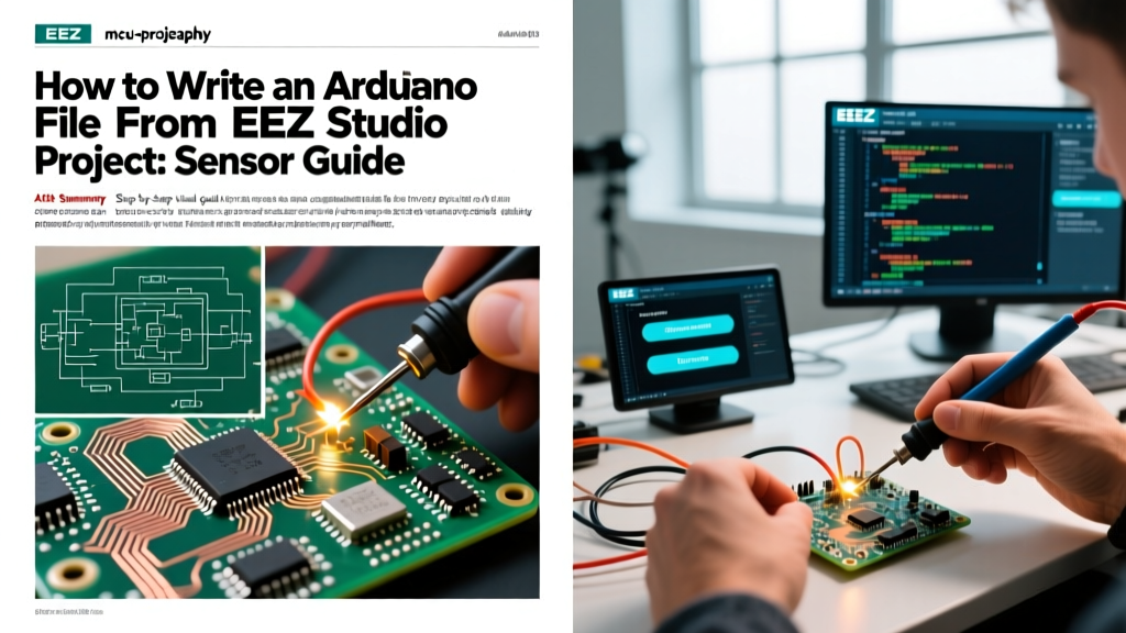
Building sensor-driven automation projects traditionally involves writing hundreds of lines of boilerplate C++ code in the Arduino IDE. However, visual programming environments are changing this workflow. If you are wondering how to write an Arduino file from EEZ Studio project files, you are tapping into one of the most powerful visual-to-code pipelines available in 2026. EEZ Studio, primarily known for its LVGL GUI builder, features a robust 'Flow' environment that allows engineers to design logic visually and compile it directly into standard Arduino .ino and .cpp files.
This guide walks through the exact process of designing a sensor-reading flow using an ESP32 and a Bosch BME280 environmental sensor, and exporting it into a fully functional Arduino sketch.
Hardware Bill of Materials (BOM)
Before initializing the software pipeline, ensure your hardware bench is prepped. The following components are optimized for 3.3V logic and I2C stability:
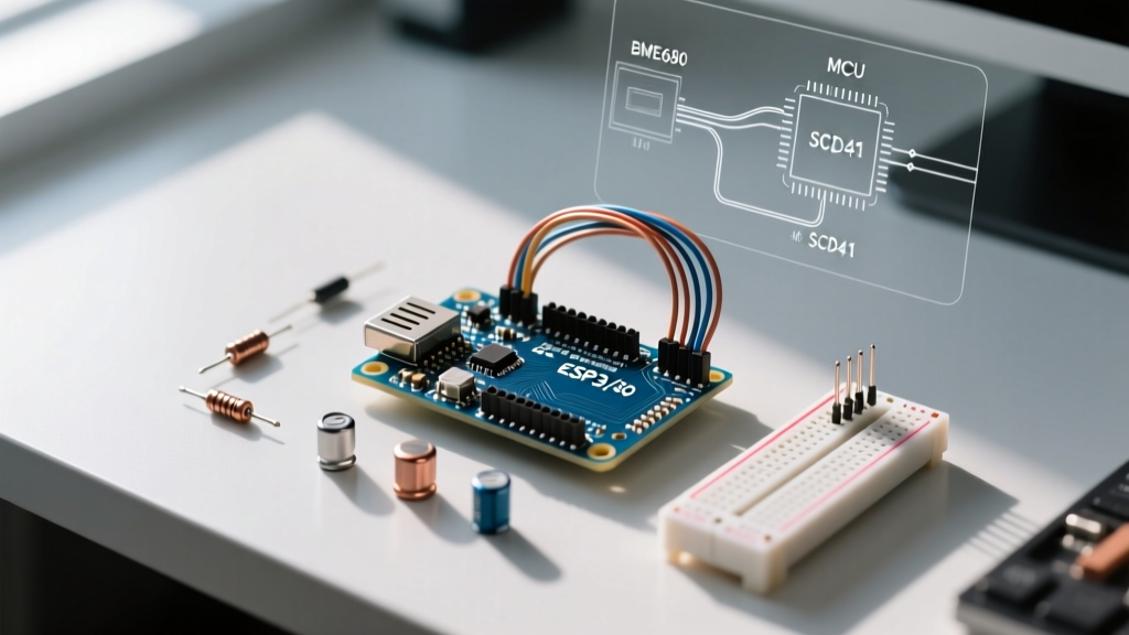
- Microcontroller: ESP32-S3 DevKitC-1 (WROOM-1 module) — Approx. $7.50. Chosen for its native USB-C and dual-core processing, ideal for handling visual flow overhead.
- Sensor: Adafruit BME280 I2C/SPI Breakout (Product ID: 2652) — Approx. $19.95. Provides temperature, humidity, and barometric pressure.
- Wiring: 4-pin JST-SH STEMMA QT cable for solderless I2C connections.
- Pull-up Resistors: 4.7kΩ (if your specific breakout board lacks onboard I2C pull-ups, though the Adafruit 2652 includes them).
Step-by-Step: Generating the Arduino File
The core challenge in EEZ Studio is that it does not natively 'know' about third-party Arduino sensor libraries out of the box. You must bridge the visual node environment with standard C++ header files. Here is the exact workflow to generate your Arduino file.
Step 1: Project Initialization and Target Selection
- Open EEZ Studio (ensure you are running the latest 2026 release, v0.9.x or newer).
- Select New Project and choose the Flow project type (not LVGL/GUI).
- Name your project (e.g.,
BME280_Sensor_Flow) and set the target platform to Arduino / ESP32. - EEZ Studio will generate a base
.eez-projectfile and a default visual canvas representing thesetup()andloop()execution threads.
Step 2: Injecting Sensor Libraries via Project Settings
This is the most common failure point. You cannot drag and drop an #include statement onto the visual canvas. You must inject it globally.
Pro-Tip: Always inject hardware-specific headers at the project level to prevent 'does not name a type' compilation errors when the Arduino IDE parses the exported file.
- Navigate to Project Settings (the gear icon in the left sidebar).
- Locate the C/C++ Includes section. Add the following lines:
#include <Wire.h>#include <Adafruit_Sensor.h>#include <Adafruit_BME280.h> - Scroll down to Global Declarations. Instantiate your sensor object here so it is accessible across all visual flow nodes:
Adafruit_BME280 bme;float tempC;
Step 3: Building the Sensor Read Flow
Now, construct the logic visually.
- In the Setup Flow: Drag a C++ Code action block onto the canvas. Inside this block, write your I2C initialization:
Wire.begin(8, 9);(using ESP32-S3 default I2C pins) andbme.begin(0x76);(the standard I2C address for the Adafruit breakout). - In the Loop Flow: Drag a Delay node and set it to 2000ms.
- Add another C++ Code action block. Write the read command:
tempC = bme.readTemperature(); - Connect the output of this block to a Log node or an LVGL display update node if you are combining Flow with a GUI.
Step 4: Exporting and Compiling the .ino File
To answer the core question of how to write an Arduino file from EEZ Studio project data: you don't 'export' it manually; you Build it.
- Click the Build icon (hammer) in the top toolbar.
- EEZ Studio's internal compiler translates the visual nodes into standard C++ syntax.
- Navigate to your project directory on your local drive and open the
/buildfolder. - Inside, you will find
main.ino,actions.cpp, andflow.cpp. These are your standard Arduino files. - Open the
/buildfolder directly in Arduino IDE 2.3.x. The IDE will automatically recognize the.inofile and tab the associated.cppfiles. - Select your ESP32-S3 board and COM port, then hit Upload.
Troubleshooting Common Export Failures
When bridging visual logic to hardware, edge cases inevitably arise. Here is how to resolve the most frequent compilation and runtime errors:
| Error Symptom | Root Cause | Solution |
|---|---|---|
'bme' was not declared in this scope |
Sensor object instantiated inside a local visual node instead of Global Declarations. | Move Adafruit_BME280 bme; to Project Settings > Global Declarations. |
Wire.h: No such file or directory |
Arduino IDE board definitions for ESP32 are outdated or missing. | Update Espressif Systems boards via Arduino IDE Boards Manager (v3.0.x or newer). |
Sensor reads NaN or -128.0 |
I2C address mismatch or missing pull-up resistors on the SDA/SCL lines. | Run an I2C scanner sketch. If address is 0x77, change bme.begin(0x76) to 0x77. |
EEZ Flow vs. Traditional Arduino IDE: Sensor Project Comparison
Is visual programming actually faster for sensor integration? Here is a matrix comparing the EEZ Studio Flow approach against traditional hand-coding in the Arduino IDE for a standard 3-sensor environmental monitoring build.
| Feature | EEZ Studio Flow | Traditional Arduino IDE |
|---|---|---|
| Initial Setup Time | 15 mins (Requires UI mapping) | 5 mins (Open IDE, start typing) |
| Logic Visualization | Excellent (Node-based flowcharts) | Poor (Relies on code comments) |
| Library Integration | Moderate (Requires manual header injection) | Excellent (Native Library Manager) |
| Debugging | Visual breakpoints, but requires rebuild | Standard Serial.print() and step-through |
| Best Use Case | Complex state machines & GUI combos | Simple, single-purpose sensor reads |
Advanced I2C Timing Considerations
When generating code via EEZ Studio, the visual execution loop runs as fast as the microcontroller allows. Environmental sensors like the BME280 require a specific oversampling and standby time configuration to prevent I2C bus lockups. According to Espressif's official I2C peripheral guidelines, injecting artificial delays between consecutive I2C transactions prevents the ESP32's hardware I2C FIFO buffer from overflowing.
In your EEZ Studio Loop flow, always place a Delay Node (minimum 100ms) between triggering a sensor read and pushing that data to an external API or display buffer. Furthermore, referencing the Arduino Wire Library documentation reminds us that the default I2C clock speed is 100kHz. If you are multiplexing multiple sensors on the same bus via a TCA9548A chip, you may need to inject Wire.setClock(400000); in your Setup C++ block to ensure timely data polling.
Final Thoughts on Visual Firmware Pipelines
Mastering how to write an Arduino file from EEZ Studio project environments fundamentally shifts your workflow from syntax management to logic architecture. By offloading the structural boilerplate to EEZ Studio's compiler, you can focus entirely on sensor calibration, data filtering, and state-machine design. For complex IoT nodes requiring both environmental sensing and local LVGL touch interfaces, this visual-to-code pipeline is currently the most efficient development path available.
For more information on the underlying architecture of the visual compiler, review the official EEZ Studio open-source repository, which details the AST (Abstract Syntax Tree) generation used to translate visual nodes into clean, human-readable C++ code.