
The Shift to Hardwired Home Automation
While wireless protocols like Matter and Thread dominate consumer smart home marketing in 2026, true reliability in critical infrastructure demands hardwired solutions. When designing robust electrical Arduino projects for home automation, microcontrollers like the ESP32 and Arduino Mega offer deterministic latency, fail-safe operation, and immunity to the RF congestion that plagues Wi-Fi and Zigbee meshes. By interfacing directly with mains voltage, RS485 bus lines, and high-torque actuators, you transition from assembling consumer gadgets to engineering permanent residential infrastructure.
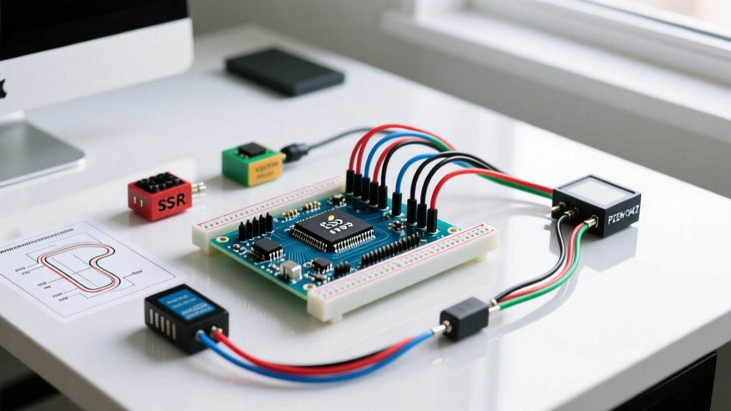
This guide details three advanced, high-voltage and high-current electrical Arduino projects tailored for home automation. We will cover zero-crossing solid-state relay (SSR) lighting control, whole-panel RS485 energy telemetry, and automated HVAC damper actuation using stepper motors.
⚠️ CRITICAL SAFETY WARNING: Working with mains voltage (120V/240V AC) is lethal. All projects involving AC line voltage must comply with NFPA 70 (National Electrical Code), specifically Article 725 regarding Class 1, 2, and 3 remote-control circuits. Always use proper galvanic isolation, double-insulated enclosures, and DIN-rail mounted terminal blocks. Never prototype mains voltage on a breadboard.
Project 1: Zero-Crossing SSR Lighting Controller
Standard mechanical relays suffer from contact arcing, acoustic noise, and eventual mechanical failure. For high-cycle home automation lighting, Solid State Relays (SSRs) are the industry standard. However, switching AC loads randomly within the sine wave generates massive Electromagnetic Interference (EMI), which can degrade the range of your home's Zigbee or Thread networks.
Component Selection and Architecture
- Microcontroller: ESP32-WROOM-32 ($5.50) - Chosen for its dual-core processing and native Wi-Fi for MQTT publishing.
- Switching Element: Omron G3MB-202P Zero-Crossing SSR ($4.20). Rated for 2A at 240VAC, it features built-in zero-crossing detection, ensuring the load is only switched when the AC voltage is at 0V, drastically reducing inrush current and EMI.
- Isolation: MOC3021 Optoisolator ($0.85) to provide galvanic separation between the 3.3V ESP32 GPIO and the SSR LED trigger.
Thermal Management and Failure Modes
A common failure mode in electrical Arduino projects using SSRs is thermal runaway. The Omron G3MB-202P has an internal voltage drop of approximately 1.5V. At a continuous load of 2A, it dissipates 3W of heat. Without a heatsink, the junction temperature will exceed the 80°C safety threshold within minutes, causing the SSR to fail in a 'closed' (ON) state—a catastrophic failure for lighting.
Solution: Mount the SSR to a 40x40x10mm aluminum finned heatsink using thermal paste. For loads exceeding 1.5A, upgrade to a panel-mount SSR like the Fotek SSR-25DA with an integrated heatsink and thermal fuse.
Project 2: RS485 Whole-Panel Energy Telemetry
Monitoring individual circuits provides granular data for home automation logic, such as triggering load-shedding routines when solar production drops. The PZEM-004T v3.0 is a highly accurate, isolated AC power meter that communicates via Modbus RTU over RS485.
Wiring the RS485 Bus
Unlike I2C, RS485 supports cable runs up to 1,200 meters, making it ideal for routing from a basement breaker panel to a first-floor server rack. You will need a MAX485 TTL-to-RS485 transceiver module ($1.50) to interface with the ESP32's hardware UART pins.
- Differential Pair: Connect the PZEM 'A' and 'B' terminals to the MAX485 'A' and 'B' pins using 24AWG twisted pair cable.
- Termination: Solder a 120-ohm resistor across the A and B lines at the furthest node on the bus to prevent signal reflection.
- Current Sensing: Use the included 100A split-core Current Transformer (CT) clamp. Pass only the hot wire through the core; passing both hot and neutral will result in a net-zero magnetic field and a 0A reading.
Modbus Addressing and Polling Logic
By default, the PZEM-004T v3.0 operates at a baud rate of 9600 with a Modbus slave address of 0x01. If you are daisy-chaining multiple monitors (e.g., one for the HVAC circuit, one for the EV charger), you must assign unique addresses using the PZEM004Tv30 Arduino library's setAddress() function before wiring them to the same RS485 bus. Poll the registers no faster than once per second to prevent bus collisions and UART buffer overflows.
According to the U.S. Department of Energy, granular smart metering and real-time energy feedback can reduce residential electricity consumption by up to 15%. Integrating this telemetry into Home Assistant allows for automated, cost-saving load management.
Project 3: NEMA 17 HVAC Damper Actuator
Motorized HVAC dampers enable zone-based climate control, directing airflow only to occupied rooms. While commercial actuators use slow, high-torque synchronous AC motors, a custom stepper motor setup offers precise, percentage-based damper positioning (e.g., opening a vent exactly 35% to balance static pressure).
Stepper Driver Tuning (VREF)
We utilize a NEMA 17HS4401 stepper motor ($14.00) paired with an A4988 stepper driver ($2.50) controlled by an Arduino Mega. The most critical step in this electrical Arduino project is tuning the current limit (VREF) on the A4988. If the current is too low, the motor will stall and miss steps, losing its positional calibration. If too high, the driver will overheat and shut down via thermal protection.
Calculation: For the 17HS4401 (rated at 1.5A/phase) and an A4988 board with 0.1Ω sense resistors, the target VREF is 0.6V. Measure the voltage between the GND pin and the VREF potentiometer with a multimeter while adjusting the screw. Ensure the 12V/24V power supply can deliver at least 3A continuous current.
Limit Switches and Homing
Stepper motors operate in open-loop; they do not know their absolute position on startup. You must install a micro limit switch (e.g., Omron D2F-01L) at the fully-closed position of the damper flap. Upon boot, the Arduino must run a homing routine: driving the motor backward at 20% speed until the limit switch triggers, establishing the 'zero' position before executing any positioning commands via the AccelStepper library.
Component Cost & Sourcing Matrix (2026)
| Component | Model / Spec | Est. Price (USD) | Primary Function |
|---|---|---|---|
| Microcontroller | ESP32-WROOM-32 DevKit | $5.50 | Wi-Fi/MQTT & GPIO Control |
| Solid State Relay | Omron G3MB-202P (Zero-Cross) | $4.20 | EMI-Free Mains Switching |
| Energy Monitor | PZEM-004T v3.0 + 100A CT | $12.50 | Modbus RTU Power Telemetry |
| RS485 Transceiver | MAX485 Module | $1.50 | TTL to Differential Bus |
| Stepper Motor | NEMA 17HS4401 (1.5A) | $14.00 | HVAC Damper Actuation |
| Stepper Driver | A4988 with Heatsink | $2.50 | Microstepping & Current Control |
Advanced Troubleshooting & Edge Cases
Ghost Triggering on Long GPIO Runs
When routing 3.3V logic signals from an ESP32 to a relay board over distances greater than 2 meters, capacitive coupling from adjacent AC wires can induce voltage spikes, causing 'ghost triggering' (relays clicking randomly). Fix: Use shielded twisted-pair cable for logic lines, connect the shield to DC ground at the microcontroller end only, and add a 10kΩ pull-down resistor directly at the SSR/MOSFET gate.
ESP32 Brownouts During Relay Switching
Switching inductive loads (like furnace blowers or older fluorescent ballasts) generates severe voltage transients on the DC rail if the power supply is inadequately filtered. This manifests as the ESP32 resetting and logging a 'Brownout detector was triggered' error. Fix: Power the ESP32 and the relay logic from completely separate DC-DC buck converters. Never share the 5V/GND rail between the microcontroller and the mechanical relay coils.
Conclusion
Transitioning from low-voltage logic to high-voltage infrastructure requires a rigorous approach to isolation, thermal management, and code compliance. By leveraging zero-crossing SSRs, RS485 telemetry, and precisely tuned stepper actuators, these electrical Arduino projects provide a foundation for a home automation system that is not only intelligent but engineered for decades of reliable, fail-safe operation. For more on the underlying silicon powering these builds, review the official Espressif ESP32 documentation to optimize your deep-sleep and interrupt routines.