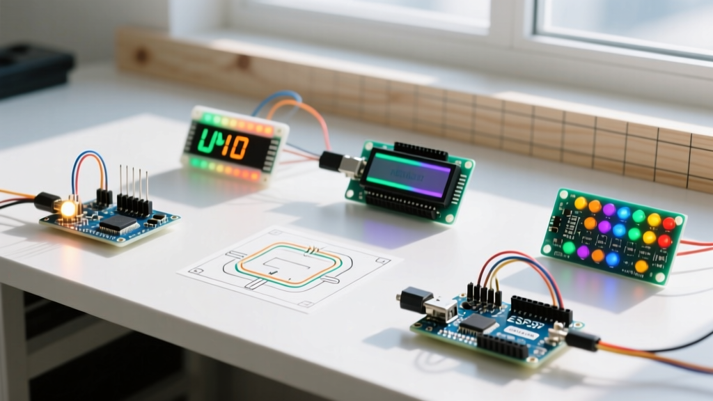

Why Start with LED Projects with Arduino?
Light-emitting diodes (LEDs) are the 'hello world' of hardware programming, but mastering them requires more than just copying a blink sketch. Building structured LED projects with Arduino teaches you foundational electronics concepts: Ohm's Law, pulse-width modulation (PWM), state machines, and power management. In 2026, while microcontrollers have evolved, the physics of driving a diode remains unchanged. This guide moves beyond basic tutorials, providing exact component specifications, circuit mathematics, and real-world troubleshooting frameworks to elevate your DIY skills.
Essential Hardware and Component Guide
Before wiring your first circuit, you need the right components. Using incorrect resistors or drawing too much current can permanently damage your microcontroller's I/O pins. Below is the exact bill of materials (BOM) for the projects in this guide.
| Component | Specification / Model | Approx. Cost (2026) | Purpose |
|---|---|---|---|
| Microcontroller | Arduino Uno R3 (ATmega328P) or R4 Minima | $27.50 - $29.99 | Main logic controller |
| Standard LEDs | 5mm Through-Hole (Red, Green, Blue) | $8.00 / 100-pack | Basic indicator lighting |
| Resistors | 150Ω, 220Ω, 330Ω (1/4W, 1% tolerance) | $6.00 / kit | Current limiting |
| Addressable LEDs | WS2812B Strip (60 LEDs/m, 5V) | $16.50 / 1-meter | Complex RGB animations |
| Sensor | GL5528 Photoresistor (LDR) | $4.00 / 10-pack | Ambient light detection |
Project 1: The Enhanced Blink (Understanding PWM and Ohm's Law)
The standard 'Blink' sketch uses digitalWrite(), which only outputs 5V (HIGH) or 0V (LOW). To fade an LED, we use Pulse Width Modulation (PWM) via analogWrite(). This rapidly switches the pin on and off, simulating analog voltage.
Calculating the Current-Limiting Resistor
Never wire an LED directly to a 5V pin. According to SparkFun's comprehensive LED tutorial, you must calculate the resistor based on the LED's Forward Voltage (Vf) and desired Forward Current (If). For a standard 5mm Red LED, Vf is typically 2.0V and max If is 20mA (0.02A).
The Math: R = (V_source - Vf) / If
R = (5V - 2.0V) / 0.02A = 150Ω.
Use a standard 150Ω or 220Ω resistor. For Blue or White LEDs (Vf ≈ 3.2V), the math yields 90Ω; use a 100Ω or 150Ω resistor.
Expert Warning: While the classic ATmega328P (Uno R3) can source up to 40mA per pin, the absolute maximum rating is a recipe for silicon degradation. Always design for a continuous 15mA to 20mA. If you are using the newer Arduino Uno R4 Minima (Renesas RA4M1 chip), consult the datasheet carefully, as some I/O ports are strictly limited to 8mA per pin.
Project 2: Non-Blocking Traffic Light Controller
Beginners often use the delay() function to time LED sequences. The problem? delay() halts the entire microcontroller, preventing it from reading sensors or accepting button inputs. A true engineering approach uses a state machine with millis().
Wiring and Logic Flow
- Wire a Red LED to Pin 4, Yellow to Pin 3, and Green to Pin 2 (all with 220Ω resistors).
- Define variables to store the
previousMillisand the currentlightState. - In the
loop(), check if the difference between currentmillis()andpreviousMillisexceeds your interval. - If it does, update the
lightStateand switch the I/O pins accordingly.
This non-blocking architecture is the foundational pattern for all advanced home automation and IoT projects, allowing your Arduino to manage LED timing while simultaneously polling Wi-Fi modules or environmental sensors.
Project 3: WS2812B Addressable RGB Strip (Intro to Libraries)
Addressable LEDs like the WS2812B (often branded as NeoPixels) contain a tiny embedded driver chip inside the LED package. You can control hundreds of them using a single digital pin. For this project, we use the industry-standard FastLED library.
Power Injection and Current Limits
This is where most beginner LED projects with Arduino fail catastrophically. A single WS2812B pixel drawing full white (Red + Green + Blue) consumes roughly 60mA. A 1-meter strip with 60 LEDs will draw 3.6 Amps at 5V.
- The Failure Mode: The Arduino's onboard 5V voltage regulator (typically an NCP1117) and the USB polyfuse are rated for roughly 500mA to 800mA max. Powering a 60-LED strip from the Arduino's 5V pin will overheat the regulator, trip the USB polyfuse, or permanently fry the board's power traces.
- The Solution: Use an external 5V power supply rated for at least 4A. Wire the power supply's 5V and GND directly to the LED strip's power rails. Crucially, you must connect the GND of the external power supply to the GND of the Arduino to establish a common ground reference for the data signal.
As detailed in the Adafruit NeoPixel Überguide, you should also place a 1000µF (6.3V or higher) electrolytic capacitor across the power supply terminals to buffer sudden current surges, and a 300Ω to 500Ω resistor on the data line to prevent voltage spikes from destroying the first pixel.
Project 4: Analog Sensor Fading (Photoresistor Integration)
Combine inputs and outputs by building an automatic night-light. A GL5528 photoresistor changes its resistance based on ambient light (roughly 10kΩ-20kΩ in daylight, dropping to 1kΩ or less in bright light, and rising to 1MΩ+ in darkness).
Building the Voltage Divider
The Arduino's ADC (Analog-to-Digital Converter) reads voltage, not resistance. You must build a voltage divider. Wire the LDR between the 5V pin and Analog Pin A0. Wire a 10kΩ pull-down resistor between A0 and GND. As light levels change, the voltage at A0 shifts between 0V and 5V. Map the analogRead() value (0-1023) to the PWM range (0-255) to smoothly fade an LED based on room darkness.
Project 5: Charlieplexing 6 LEDs on 3 Pins
When you run out of I/O pins, Charlieplexing leverages the tri-state logic of microcontrollers (HIGH, LOW, and INPUT/high-impedance) to control multiple LEDs. The formula for Charlieplexing is n² - n, where n is the number of pins. With 3 pins, you can control 6 individual LEDs.
By setting one pin to HIGH (Source), one pin to LOW (Sink), and the third pin to INPUT (effectively disconnecting it from the circuit), you can route current through specific LEDs in anti-parallel pairs. This requires complex wiring and rapid software multiplexing (refreshing the LEDs faster than the human eye can see, typically >60Hz), but it is a brilliant exercise in understanding digital logic states and circuit routing.
Troubleshooting Common LED Circuit Failures
Even with perfect code, hardware issues will arise. Use this diagnostic matrix to solve common problems encountered in LED projects with Arduino.
| Symptom | Probable Cause | Engineering Fix |
|---|---|---|
| LED is extremely dim | Wrong resistor value or floating ground | Verify resistor bands with a multimeter; ensure GND is shared. |
| MCU resets randomly | Overcurrent brownout on the 5V rail | Move high-draw LEDs to an external PSU; check for short circuits. |
| Addressable LEDs flicker | Data signal degradation or missing pull-up | Add a 330Ω resistor on the data line; keep data wires under 50cm. |
| Colors are wrong on WS2812B | Incorrect RGB byte order in library | Change FastLED color order from RGB to GRB in the setup macro. |
For deeper hardware diagnostics and pinout verification, always refer to the official Arduino LED documentation. Mastering these five projects transitions you from a hobbyist copying code to an electronics builder capable of designing robust, scalable, and safe lighting automation systems.