
Beyond Line-Followers: The Smart Home Rover
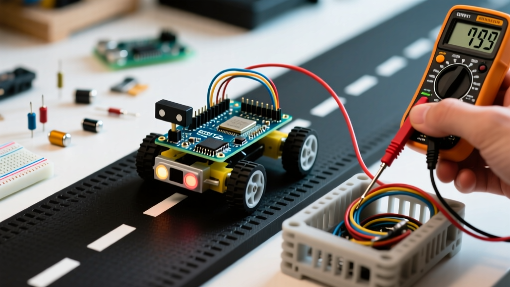
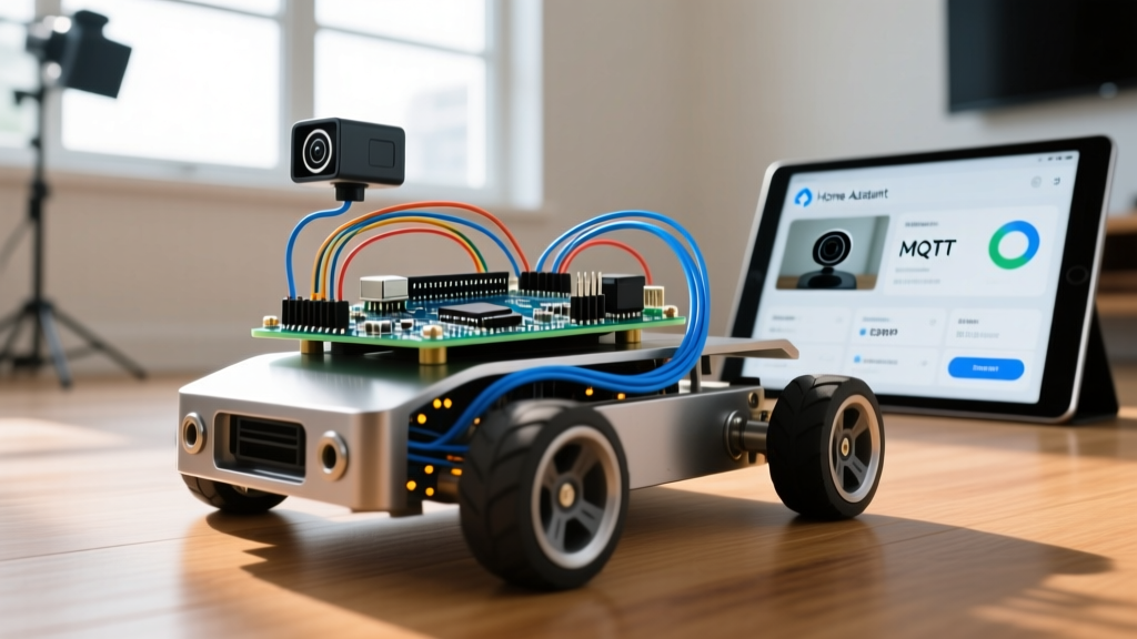
Most DIY robotics tutorials stop at basic obstacle avoidance or infrared line-following. However, as smart home ecosystems mature in 2026, the true potential of an arduino car project lies in its integration with home automation networks. By upgrading the standard rover into an MQTT-connected indoor patrol vehicle, you can trigger physical actions, monitor remote rooms, and integrate mobile telemetry directly into your Home Assistant dashboard.
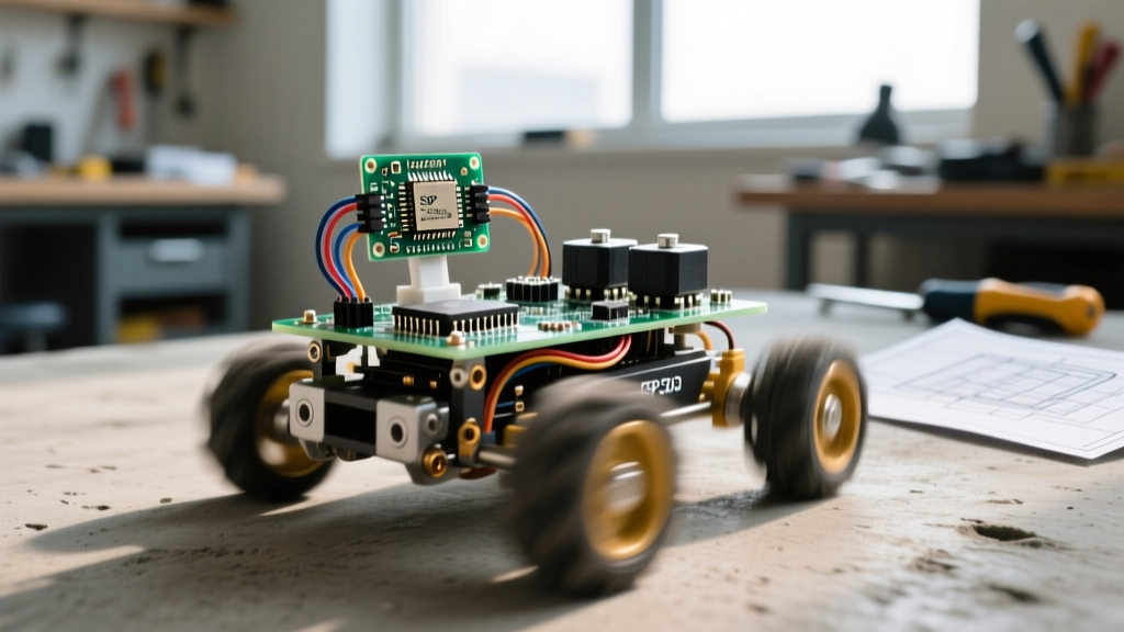
In this comprehensive guide, we will build a 2WD Home Assistant Security Rover using the Arduino Uno R4 WiFi. Unlike legacy Uno R3 builds that require bulky external ESP8266 breakout boards, the R4 WiFi features a native ESP32-S3 co-processor, allowing seamless MQTT communication, over-the-air (OTA) updates, and real-time telemetry streaming without sacrificing the classic Arduino shield form factor.
Bill of Materials (2026 Pricing)
To ensure reliability, we are bypassing cheap, high-failure-rate clone components. Below is the verified BOM for a robust home automation rover.
| Component | Specific Model / Part | Est. Price | Purpose |
|---|---|---|---|
| Microcontroller | Arduino Uno R4 WiFi (ABX00087) | $27.50 | Core logic & native MQTT WiFi |
| Motor Driver | L298N Dual H-Bridge Module | $4.50 | High-current motor switching |
| Chassis & Motors | Acrylic 2WD Kit w/ TT Gear Motors | $14.00 | Locomotion and mounting |
| IMU Sensor | MPU-6050 Gyroscope/Accelerometer | $3.50 | Z-axis drift correction (PID) |
| Ranging Sensor | HC-SR04 Ultrasonic (5V tolerant) | $2.00 | Obstacle detection |
| Power Source | 2x 18650 Li-ion Cells (2S 7.4V) | $12.00 | High-discharge mobile power |
| Voltage Regulator | LM2596 Buck Converter Module | $2.50 | Steps 7.4V down to stable 5V |
| Decoupling Caps | 0.1μF Ceramic & 100μF Electrolytic | $1.00 | EMI suppression & ripple filtering |
Total Estimated Cost: $67.00
Critical Engineering: Power Delivery and EMI Mitigation
The number one reason amateur arduino car projects fail during deployment is poor power management and Electromagnetic Interference (EMI). When TT motors spin, they generate massive voltage spikes and RF noise that will instantly reset your microcontroller or drop your WiFi connection.
The L298N Voltage Drop and Brownout Problem
A common mistake is routing battery power through the L298N’s onboard 5V linear regulator to power the Arduino. The L298N has a voltage drop of roughly 1.5V to 2.0V. If your 2S Li-ion battery drops to 6.8V under load, the regulator outputs barely 4.8V. Furthermore, the ESP32-S3 on the Uno R4 WiFi can draw up to 350mA during WiFi transmission spikes, which will overheat and shut down the L298N’s weak linear regulator.
The Fix: Disable the 5V jumper on the L298N. Wire the 7.4V battery directly to a dedicated LM2596 buck converter. Adjust the buck converter’s potentiometer with a multimeter to output exactly 5.0V, and wire this directly to the Arduino’s 5V pin (bypassing the onboard USB regulator). This guarantees clean, high-current power to the MCU regardless of motor load.
RF Noise and WiFi Dropouts
Brushed TT motors act as broadband RF emitters. If you place an ESP32 or Uno R4 WiFi within 10cm of unshielded motors, the 2.4GHz WiFi signal will experience severe packet loss.
- Capacitor Soldering: Solder a 0.1μF ceramic capacitor directly across the two terminals of each motor. Additionally, solder a 0.1μF capacitor from each terminal to the metal casing of the motor.
- Physical Separation: Mount the Arduino Uno R4 on the top tier of the acrylic chassis, as far from the motor axles as possible.
Drift Correction: Implementing MPU-6050 PID Control
Standard TT gear motors have a manufacturing tolerance that results in a 10-15% RPM variance between the left and right wheels. Without correction, your rover will veer off course, making automated home patrols impossible. By mounting an MPU-6050 IMU flat on the chassis, we can read the Z-axis angular velocity (yaw rate) and feed it into a simple Proportional-Integral-Derivative (PID) loop to dynamically adjust the PWM values sent to the L298N, ensuring perfectly straight navigation down your home’s hallways.
Wiring Pinout Matrix
Ensure all grounds (Battery, L298N, Buck Converter, and Arduino) are tied together in a single star-ground topology to prevent ground loops.
| Arduino Uno R4 Pin | Target Component | Function |
|---|---|---|
| D5 (PWM) | L298N ENA | Left Motor Speed Control |
| D4 | L298N IN1 | Left Motor Direction A |
| D7 | L298N IN2 | Left Motor Direction B |
| D6 (PWM) | L298N ENB | Right Motor Speed Control |
| D8 | L298N IN3 | Right Motor Direction A |
| D9 | L298N IN4 | Right Motor Direction B |
| A4 (SDA) | MPU-6050 SDA | I2C Data (with 4.7kΩ pull-up) |
| A5 (SCL) | MPU-6050 SCL | I2C Clock (with 4.7kΩ pull-up) |
| D2 | HC-SR04 Echo | Ultrasonic Return Signal |
| D3 | HC-SR04 Trig | Ultrasonic Trigger Pulse |
MQTT Telemetry and Home Assistant Integration
To transform this build from a standalone toy into a genuine home automation node, we utilize the MQTT protocol. According to the MQTT Foundation, this lightweight publish/subscribe protocol is ideal for constrained devices and unreliable networks, making it perfect for a moving rover transitioning between different WiFi access points in a large home.
The Arduino uses the ArduinoMqttClient and WiFiS3 libraries to connect to your local Mosquitto broker. It publishes a JSON payload to the topic home/rover/patrol/telemetry every 5 seconds.
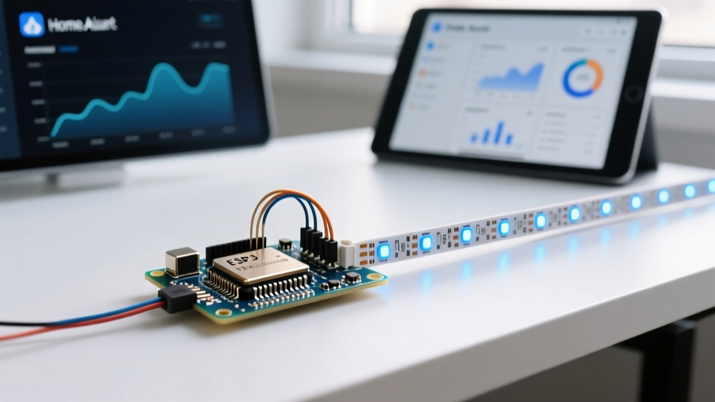
Pro-Tip for 2026 HA Deployments: Use Home Assistant’s native MQTT Discovery feature. By publishing a properly formatted configuration payload to the homeassistant/sensor/rover/config topic on boot, the rover will automatically appear in your HA device registry without manual YAML mapping for every sensor.
Home Assistant MQTT YAML Configuration
If you prefer manual configuration, add the following to your configuration.yaml to track the rover’s battery and ultrasonic proximity data:
mqtt:
  sensor:
    - name: "Rover Battery Voltage"
      state_topic: "home/rover/patrol/telemetry"
      value_template: "{{ value_json.batt_v }}"
      unit_of_measurement: "V"
      device_class: voltage
    - name: "Rover Front Clearance"
      state_topic: "home/rover/patrol/telemetry"
      value_template: "{{ value_json.dist_cm }}"
      unit_of_measurement: "cm"
      device_class: distance
Troubleshooting Edge Cases
Even with meticulous wiring, real-world home environments introduce unique failure modes. Here is how to diagnose and resolve them:
- I2C Bus Lockups: If the MPU-6050 stops responding mid-patrol, motor EMI is likely corrupting the I2C SDA/SCL lines. Solution: Add 4.7kΩ pull-up resistors to 5V on both I2C lines and implement a software watchdog timer (WDT) in your Arduino sketch to reset the I2C bus if a timeout occurs.
- Motor Stalling on Carpet: TT motors lack the torque for high-pile carpets, causing current spikes that trigger the L298N’s thermal shutdown. Solution: Upgrade to N20 metal gearmotors with a TB6612FNG MOSFET-based driver, which offers vastly superior efficiency and lower voltage drop compared to the bipolar L298N.
- WiFi Roaming Latency: As the rover moves from the living room to the bedroom, it may cling to a weak 2.4GHz mesh node. Solution: Implement Fast BSS Transition (802.11r) on your home router, or program the Arduino to monitor RSSI values and force a WiFi reconnect if the signal drops below -75dBm.
Final Calibration and Deployment
Before setting your rover loose in your home, perform a static load test. Elevate the chassis so the wheels are off the ground. Open the Home Assistant MQTT integration logs and monitor the telemetry stream. Verify that the battery voltage remains stable above 7.0V when you command full-speed PWM outputs via MQTT.
Once calibrated, you can create Home Assistant automations. For example, configure a trigger that deploys the rover from its charging dock to patrol the kitchen whenever your smart home security system detects motion after midnight. By treating your arduino car project not as an isolated toy, but as a mobile IoT node, you unlock a new dimension of physical home automation that static sensors simply cannot achieve.