
Why Most Arduino Servo Motor Projects Fail Out of the Gate
When exploring arduino servo motor projects, beginners almost universally start with the TowerPro SG90 micro-servo. While fine for a simple sweeping radar display, the SG90's 1.8 kg-cm torque and fragile nylon gears disintegrate under real-world mechanical loads. Furthermore, sensor-driven feedback loops often result in violent 'hunting' (jitter), stripping the gears and browning out the microcontroller. According to the Arduino Servo Library Documentation, standard hobby servos require precise pulse widths between 1000 and 2000 microseconds; any power sag disrupts this timing, causing erratic behavior.
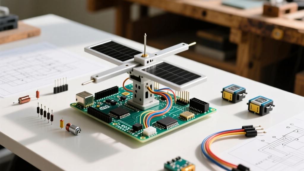
To elevate your builds, we are moving past basic sweeping and constructing a Dual-Axis Sensor-Driven Smart Sun Tracker. This project uses light sensors to continuously orient a solar panel perpendicular to the sun, maximizing energy harvest. By leveraging the 14-bit ADC of the modern Arduino Uno R4 Minima and implementing software hysteresis, we eliminate the mechanical jitter that plagues amateur sensor-driven builds.
The Core Problem: Power Starvation and Ground Loops
The number one failure mode in advanced servo projects is attempting to power high-torque servos directly from the Arduino's 5V pin. The Arduino Uno R4's onboard voltage regulator and USB traces are not designed to supply the stall current of heavy-duty servos.
- SG90 Micro Servo: Draws ~200mA operating, up to 700mA at stall.
- MG996R Metal Gear Servo: Draws ~500mA operating, up to 2.5A at stall (at 6V).
If an MG996R hits a mechanical bind and stalls, it will pull 2.5A. If powered via the Arduino, this will instantly trip the USB port's overcurrent protection or melt the board's internal traces. The solution is an isolated, high-current buck converter with a shared common ground.
Bill of Materials (BOM) & Cost Breakdown
Below is the optimized component list for a robust, dual-axis tracker capable of handling a 10W to 20W mini solar panel (approx. 300g payload).
| Component | Specific Model | Qty | Est. Cost (2026) | Engineering Notes |
|---|---|---|---|---|
| Microcontroller | Arduino Uno R4 Minima | 1 | $22.00 | Features a 14-bit ADC (vs 10-bit on R3) for ultra-fine light gradient detection. |
| Servos | TowerPro MG996R (Metal Gear) | 2 | $13.00 | 13 kg-cm torque. Ensure you buy the 180-degree version, not 270-degree. |
| Light Sensors | GL5528 LDR + 10kΩ Resistors | 4 | $3.00 | Forming 4 distinct voltage dividers for X/Y axis differential tracking. |
| Power Supply | LM2596 Buck Converter Module | 1 | $2.50 | Must be manually tuned to 5.2V to compensate for wire voltage drop. |
| Power Source | 12V 5A Switching PSU | 1 | $14.00 | Feeds the buck converter. Do not use 9V batteries; they cannot supply the amperage. |
| Chassis | 3D Printed PETG / Laser Cut Acrylic | 1 | $10.00 | PETG is mandatory; PLA will warp in direct sunlight. |
Sensor Array Design: Overcoming ADC Noise
For light tracking, we use four GL5528 Light Dependent Resistors (LDRs) arranged in a cross pattern, separated by a 3D-printed cross-shaped baffle. The baffle ensures that when the tracker is perfectly aligned with the light source, all four LDRs receive equal illumination. When misaligned, the baffle casts a shadow on the trailing LDRs.
The Voltage Divider Math
LDRs change resistance based on lux. To read this with the Arduino, we must convert resistance to voltage using a voltage divider circuit. As detailed in the SparkFun Voltage Divider Tutorial, the formula is:
Vout = Vin × (R_fixed / (R_LDR + R_fixed))
Using a 10kΩ fixed resistor and a 5V reference, a typical GL5528 (which drops to ~5kΩ in bright sunlight) will output roughly 1.66V. In shadows (resistance spikes to ~50kΩ), the output drops to ~0.83V.
Leveraging the Uno R4's 14-Bit ADC
Legacy Arduino Uno R3 boards use a 10-bit ADC, mapping 0-5V to integer values between 0 and 1023. This means each step represents ~4.8mV. In bright conditions where the LDR curve flattens, a 4.8mV resolution might not detect subtle shadow changes, leading to a 'dead zone' where the tracker stops moving.
The Arduino Uno R4 Minima features a 14-bit ADC. By adding analogReadResolution(14); in your setup loop, the mapping expands from 0 to 16383. Each step now represents just 0.3mV. This massive increase in granularity allows the microcontroller to detect micro-shadows cast by the baffle, resulting in incredibly smooth, precise tracking without needing expensive operational amplifiers.
Algorithm Logic: Implementing Hysteresis (Anti-Jitter)
The most critical software concept in sensor-driven Arduino servo motor projects is hysteresis. If you simply command the servo to move whenever the Left LDR reads higher than the Right LDR, the system will rapidly oscillate back and forth around the center point. This 'hunting' will overheat the servo's internal DC motor and strip the potentiometer gears within minutes.
Expert Tip: You must implement a 'deadband' or hysteresis threshold. The servo should only actuate if the differential between opposing sensors exceeds a specific value (e.g., 150 ADC units on a 14-bit scale).
Sample Logic Flow for the X-Axis:
int leftLDR = analogRead(A0);
int rightLDR = analogRead(A1);
int tolerance = 150; // 14-bit deadband

if (abs(leftLDR - rightLDR) > tolerance) {
  if (leftLDR > rightLDR) {
    servoX.write(currentX + 1); // Increment slowly
  } else {
    servoX.write(currentX - 1);
  }
  delay(50); // Mechanical settling time
}
By incrementing the servo position by just 1 degree per loop iteration and enforcing a 50ms delay, we allow the mechanical assembly to settle and the LDRs to stabilize before taking the next reading. This completely eliminates high-frequency jitter.
Wiring Architecture & Ground Loops
Proper wiring is non-negotiable when mixing high-current inductive loads (servos) with sensitive analog sensors (LDRs). If you share the same ground wire for the servo power return and the analog sensor ground, the back-EMF and voltage drops from the servo motor will introduce massive noise into your analog readings.
The Star Ground Topology
- Connect the negative terminal of the 12V PSU to the ground IN of the LM2596 buck converter.
- Connect the ground OUT of the LM2596 to the Ground rail on your breadboard/PCB.
- Connect the Arduino Uno R4's GND pin to this exact same ground rail.
- Connect the black (ground) wires of both MG996R servos to this ground rail.
- Connect the LDR voltage divider grounds to this ground rail.
This 'Star Ground' ensures that high-current spikes from the servos return directly to the power source without passing through the microcontroller's delicate ground traces.
Real-World Failure Modes & Troubleshooting
Even with perfect code, physical deployments of solar trackers face environmental edge cases. According to the National Renewable Energy Laboratory (NREL), while dual-axis tracking increases yield, mechanical reliability in outdoor environments remains the primary point of failure for DIY systems.
- Wind Loading & Stall Currents: A sudden gust of wind pushing against the solar panel can force the MG996R servo backward. The servo's internal circuit will fight this, drawing stall current (2.5A) continuously until it overheats. Fix: Implement a software timeout. If the ADC differential remains high but the servo position hasn't changed over 20 iterations, cut the servo signal and trigger a fault state.
- Cloud Cover Confusion: On heavily overcast days, ambient light is diffuse. The shadow cast by the baffle disappears, and the LDRs read equally low values, potentially causing the tracker to drift randomly due to ADC noise. Fix: Add a global 'sleep mode'. If the average reading of all four LDRs drops below a specific threshold (indicating night or heavy storm), lock the servos in a stow position (usually facing straight up or east) to save power and prevent wind damage.
- Potentiometer Wear: Standard hobby servos use cheap carbon-track potentiometers for positional feedback. Constant micro-adjustments will wear a physical groove into the carbon, creating dead spots. Fix: The hysteresis deadband mentioned earlier is your primary defense. For mission-critical 24/7 deployments, upgrade to brushless gimbal motors with magnetic encoders (like the AS5048B), though this increases the BOM cost by roughly $60 per axis.
Final Calibration Steps
Before mounting your solar panel, power the system indoors using a single directional light source (like a halogen desk lamp). Map the physical 180-degree sweep of your servo to the software limits. Ensure your servo.attach() limits are set correctly (e.g., servoX.attach(9, 600, 2400);) to prevent the servo from mechanically binding against its internal hard stops, which will instantly spike the current draw and trigger the buck converter's thermal shutdown.
By respecting power delivery physics, leveraging the Uno R4's high-resolution ADC, and coding defensive hysteresis, you transform a frustrating toy into a highly efficient, sensor-driven automated solar harvester.