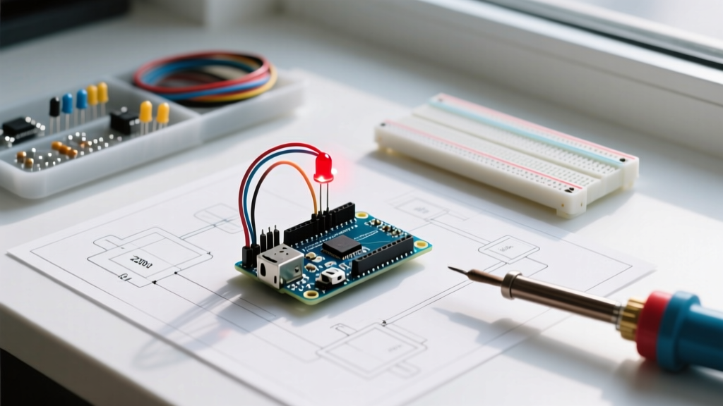

The Rite of Passage: Your First Blinking LED Arduino Project
Every embedded systems engineer, IoT hobbyist, and robotics enthusiast shares a common origin story: the blinking LED Arduino project. Often referred to as the 'Hello World' of microcontrollers, this foundational exercise teaches you the core loop of hardware programming—configuring pins, writing digital states, and managing timing. As of 2026, while the Arduino ecosystem has expanded with the powerful Renesas-based Uno R4 series, the classic ATmega328P-based Uno R3 remains the undisputed king for absolute beginners due to its massive legacy library support and widespread availability.
In this comprehensive guide, we will move beyond simply copying and pasting code. You will learn the underlying electronics principles, including Ohm's Law calculations for current limiting, the physical anatomy of breadboards, and the critical difference between blocking and non-blocking code architectures. By the end, you will not just have a blinking light; you will have a functional understanding of digital I/O (Input/Output) operations.
Bill of Materials (BOM) and 2026 Pricing
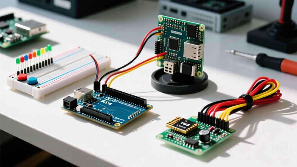
To build this circuit, you need a minimal set of components. You can purchase these individually or as part of a comprehensive starter kit. Below is a breakdown of the required hardware with current market pricing.
| Component | Specification / Model | Estimated Cost (USD) | Notes |
|---|---|---|---|
| Microcontroller | Arduino Uno R3 (Genuine or Clone) | $14.00 - $27.50 | Clones (e.g., Elegoo) use the CH340 USB-C serial chip and cost ~$14. |
| LED | 5mm Through-Hole (Red, Green, or Blue) | $0.05 | Standard diffused lens. Forward voltage varies by color. |
| Resistor | 220Ω or 330Ω Carbon Film (1/4W) | $0.02 | Crucial for current limiting to prevent LED burnout. |
| Breadboard | 830 Tie-Point Solderless Breadboard | $4.50 | Provides spring-clip connections without soldering. |
| Jumper Wires | Male-to-Male (M2M) Dupont Wires | $0.10 | 22 AWG stranded copper is standard. |
Pro Tip: If you are just starting, the Elegoo Super Starter Kit (retailing around $35.99 in 2026) includes the Uno R3 clone, a breadboard, hundreds of LEDs, resistors, and sensors, offering immense long-term value.
Understanding the Hardware: LEDs and Resistors
Before inserting components into the breadboard, you must understand their physical and electrical properties. An LED (Light Emitting Diode) is a polarized component, meaning current can only flow in one direction.
- The Anode (+): The longer leg of the LED. This connects to the positive voltage source (the Arduino digital pin).
- The Cathode (-): The shorter leg, located next to the flat notch on the LED's plastic rim. This connects to Ground (GND).
According to the official Arduino digital pins documentation, the ATmega328P microcontroller can source a maximum of 40mA per I/O pin, but the recommended safe continuous operating current is 20mA. If you connect an LED directly to a 5V pin without a resistor, the LED will draw excessive current, overheat, and fail catastrophically—a failure mode affectionately known in the community as 'letting the magic smoke out.'
Calculating the Correct Resistor (Ohm's Law)
To determine the exact resistor needed, we use Ohm's Law: R = (V_source - V_forward) / I_forward. For a deep dive into these electrical principles, the SparkFun Ohm's Law tutorial is an excellent resource.
| LED Color | Typical Forward Voltage (Vf) | Target Current (If) | Calculated Resistor | Standard E12 Value to Use |
|---|---|---|---|---|
| Red | 2.0V | 20mA (0.02A) | (5V - 2.0V) / 0.02 = 150Ω | 220Ω |
| Green | 2.2V | 20mA (0.02A) | (5V - 2.2V) / 0.02 = 140Ω | 220Ω |
| Blue / White | 3.2V | 20mA (0.02A) | (5V - 3.2V) / 0.02 = 90Ω | 100Ω or 220Ω |
Using a 220Ω or 330Ω resistor is a safe, universal choice for any standard 5mm LED on a 5V Arduino logic system. It limits the current to roughly 14mA for a red LED, which is well within the safe operating area and still provides ample brightness.
Step-by-Step Wiring Guide
- Place the Resistor: Insert one leg of the 220Ω resistor into digital pin 8 (D8) on the Arduino Uno. Insert the other leg into row 10, column 'a' on your breadboard.
- Insert the LED: Insert the Anode (long leg) into row 10, column 'b'. This connects it to the resistor via the internal metal spring clips of the breadboard. Insert the Cathode (short leg) into row 11, column 'b'.
- Complete the Circuit: Take a male-to-male jumper wire. Connect one end to row 11, column 'c' (sharing the same tie-point as the LED cathode). Connect the other end to any of the GND (Ground) pins on the Arduino's POWER header.
Hardware Check: Always double-check your breadboard power rails. While this specific project uses direct pin-to-component wiring, future projects will use the red (+) and blue (-) rails. Never connect 5V directly to the blue ground rail, or you will short-circuit the Arduino's onboard polyfuse or voltage regulator.
The Code: Blocking vs. Non-Blocking Architecture
Most beginner tutorials rely exclusively on the delay() function. While easy to read, delay() is a 'blocking' function. When the microcontroller executes delay(1000), it stops all other processing for one second. It cannot read sensors, monitor buttons, or communicate via serial. To build robust IoT devices in 2026, you must learn non-blocking code using millis().
Method 1: The Beginner Approach (Blocking)
This is the standard 'Hello World' code. Upload this via the Arduino IDE (version 2.3+ recommended).
const int LED_PIN = 8;

void setup() {
  pinMode(LED_PIN, OUTPUT);
}

void loop() {
  digitalWrite(LED_PIN, HIGH); // Turn LED ON (5V)
  delay(1000);                 // Pause for 1000ms (1 second)
  digitalWrite(LED_PIN, LOW);  // Turn LED OFF (0V)
  delay(1000);                 // Pause for 1000ms
}
Method 2: The Professional Approach (Non-Blocking)
By tracking the system's uptime using millis(), we allow the microcontroller to multitask. This is the exact paradigm used in professional RTOS (Real-Time Operating Systems) environments.
const int LED_PIN = 8;
int ledState = LOW;
unsigned long previousMillis = 0;
const long interval = 1000;

void setup() {
  pinMode(LED_PIN, OUTPUT);
}

void loop() {
  unsigned long currentMillis = millis();

  // Check if the interval has passed without blocking the CPU
  if (currentMillis - previousMillis >= interval) {
    previousMillis = currentMillis;

    // Toggle the LED state
    if (ledState == LOW) {
      ledState = HIGH;
    } else {
      ledState = LOW;
    }
    digitalWrite(LED_PIN, ledState);
  }

  // The CPU is free here to read sensors or handle Wi-Fi tasks!
}
Troubleshooting Matrix: Failure Modes and Fixes
Hardware rarely works perfectly on the first attempt. Use this diagnostic matrix to identify and resolve common issues encountered during the blinking LED Arduino project.
| Symptom | Probable Cause | Multimeter Test / Solution |
|---|---|---|
| LED remains completely dark | Reversed polarity or dead LED | Flip the LED legs. If still dark, test LED with a multimeter's diode mode (should read ~1.8V-3.2V). |
| LED is extremely dim | Resistor value too high or poor breadboard contact | Verify resistor color bands (Red-Red-Brown for 220Ω). Wiggle wires to ensure spring-clip grip. |
| LED flashes once, then stays on | Missing second delay() in loop | Check code. If the second delay is missing, the LOW state executes so fast it appears continuously ON due to persistence of vision. |
| Arduino gets hot to the touch | Short circuit on 5V rail | Disconnect USB immediately. Check for stray wire strands bridging 5V and GND on the breadboard. |
| Upload fails (avrdude error) | Wrong COM port or missing CH340 driver | In IDE, go to Tools > Port. If using a clone, install the latest CH340/CH341 USB-Serial drivers for your OS. |
Next Steps and Scaling Up
Once you have mastered the single blinking LED Arduino project, the immediate next step is to scale the hardware. Try adding three more LEDs to pins 9, 10, and 11 to create a sequential 'chaser' light effect. From there, integrate a push-button on pin 2 using digitalRead() and internal pull-up resistors (INPUT_PULLUP) to manually control the blink rate. This foundational knowledge of digital outputs, current limiting, and non-blocking timing loops forms the bedrock upon which all advanced home automation and IoT robotics projects are built.