
The Ultimate Stepping Stone: Why This Build Matters
When makers search for beginner projects arduino tutorials, they are often met with outdated advice: using 9V alkaline batteries that sag under load, or relying on the highly inefficient L298N motor driver. In 2026, the standard for entry-level robotics has evolved. The Arduino Uno R4 Minima, powered by the Renesas RA4M1 ARM Cortex-M4F processor, is now the go-to microcontroller, offering hardware PWM and a 14-bit ADC that completely changes how we handle motor control and sensor noise.
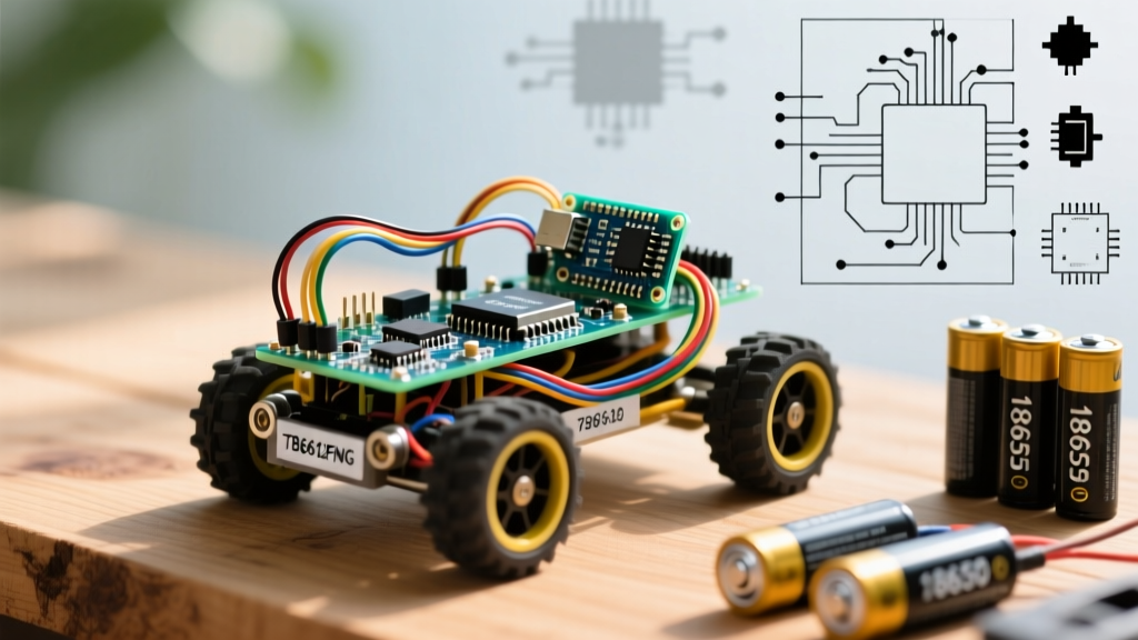
This guide strips away the fluff and walks you through building a professional-grade 2WD Obstacle-Avoiding Rover. By focusing on power architecture, efficient MOSFET motor driving, and non-blocking C++ state machines, this project bridges the gap between a toy and a legitimate engineering prototype.
Bill of Materials (BOM) & Component Selection
Selecting the right components is where most robotics builds fail before they even begin. Below is the optimized 2026 BOM, prioritizing efficiency and logic-level compatibility.
| Component | Specific Model / Part | Est. Cost | Why We Chose It |
|---|---|---|---|
| Microcontroller | Arduino Uno R4 Minima | $27.50 | ARM Cortex-M4F, USB-C, 14-bit ADC, 3.3V/5V tolerant logic. |
| Motor Driver | TB6612FNG Dual Carrier | $6.50 | MOSFET H-bridge. Drops only ~0.5V compared to the L298N's 2V BJT drop. |
| Motors & Chassis | TT Gearmotors (1:48) + Acrylic Base | $12.00 | Standard 3-6V DC motors with enough torque for indoor surfaces. |
| Sensor | HC-SR04+ (Plus Version) | $3.50 | The '+' version natively supports 5V logic without a voltage divider on the Echo pin. |
| Power Source | 2x Molicel P26A 18650 + 2S Holder | $14.00 | High-discharge Li-ion cells capable of sustaining motor stall currents. |
Power Architecture: The #1 Point of Failure
Expert Insight: Never use a standard 9V rectangular alkaline battery for a robotics chassis. The internal resistance is too high. When your TT motors stall or start up, they draw up to 800mA each. A 9V alkaline will experience severe voltage sag, instantly brownout-resetting your Arduino.
For this build, we use a 2S (2-cell series) 18650 Lithium-Ion configuration. Two Molicel P26A cells in series provide a nominal 7.4V (8.4V fully charged). According to Adafruit's Motor Selection Guide, understanding stall current is critical. The TT gearmotors have a stall current of roughly 800mA at 6V. With two motors, your peak draw is 1.6A. The Molicel P26A cells can comfortably deliver 10A+ continuously, ensuring the voltage rail remains stiff even during sharp, high-friction turns.
Wiring the Power: Run the 2S battery pack's positive lead to the TB6612FNG's VM (Motor Power) pin and the Arduino's VIN pin. Connect all grounds (Battery GND, Motor Driver GND, Arduino GND, Sensor GND) to a single common ground bus. Ground loops cause erratic sensor readings and are the silent killer of beginner projects arduino builds.
Motor Control: Ditching the L298N for the TB6612FNG
The L298N is a relic. It uses bipolar junction transistors (BJTs) which inherently drop 1.5V to 2V across the H-bridge. If you feed it 7.4V, your motors only see ~5.5V, wasting energy as heat. The Pololu TB6612FNG carrier uses MOSFETs, dropping a mere 0.5V total. Your motors get the voltage they need, and your battery life increases by up to 30%.
Wiring the TB6612FNG
- VCC: Connect to Arduino 5V (Logic power).
- VM: Connect to Battery Positive (7.4V).
- GND: Connect to Common Ground.
- STBY (Standby): Must be pulled HIGH (connect to 5V) to enable the driver.
- PWMA / PWMB: Connect to Arduino Pins 5 and 6 (Hardware PWM pins on the R4 Minima).
- AIN1, AIN2, BIN1, BIN2: Connect to digital pins 4, 7, 8, and 9 for directional logic.
Sensor Integration: The Decoupling Trick
The HC-SR04+ uses acoustic transducers that draw sharp, high-current spikes when emitting the 40kHz ultrasonic burst. If your power rails are shared with the microcontroller, these spikes can cause the Arduino's brownout detector (BOD) to trigger a reset.
The Fix: Solder a 100µF electrolytic capacitor directly across the VCC and GND pins on the back of the HC-SR04+ sensor. This acts as a local energy reservoir, absorbing the acoustic spike and keeping the main logic rail clean. Mount the sensor at least 3 inches above the chassis base to prevent acoustic reflections from the front caster wheel from causing false 'obstacle detected' readings.
Non-Blocking C++ Control Logic
Most tutorials use the delay() function to wait for the rover to turn. In robotics, delay() is fatal—it blinds the robot to its environment while it waits. We use a millis() based state machine to keep the rover constantly scanning.
Furthermore, the Arduino Uno R4 Minima documentation highlights its enhanced timer capabilities. We set the PWM frequency to 1kHz to ensure the TB6612FNG switches cleanly without emitting high-pitched audible whine from the motors.
// Simplified State Machine Snippet for Obstacle Avoidance
unsigned long lastPingTime = 0;
const int pingInterval = 35; // 35ms prevents acoustic cross-talk
int distance = 0;

void loop() {
  // Non-blocking sensor ping
  if (millis() - lastPingTime >= pingInterval) {
    distance = readUltrasonic();
    lastPingTime = millis();
  }

  // Navigation Logic
  if (distance < 20 && distance > 0) {
    // Obstacle detected: Reverse and spin
    setMotors(-150, -150);
  } else {
    // Path clear: Drive forward
    setMotors(200, 200);
  }
}
Troubleshooting Matrix: Real-World Failure Modes
Even with perfect wiring, physics and electronics often disagree. Use this matrix to diagnose common issues specific to this chassis configuration.
| Symptom | Root Cause | Engineering Fix |
|---|---|---|
| Robot veers slightly to one side when driving 'straight' | TT gearmotors have high manufacturing variances; no two motors spin at the exact same RPM. | Implement a software trim value. Reduce PWM to the faster motor by 5-10% until the chassis tracks straight. |
| Sensor randomly reads '0' or '4000' (max timeout) | Acoustic cross-talk or 5V logic noise on the Echo pin. | Increase pingInterval to 40ms. Ensure you are using the HC-SR04+ model, not the standard 3.3V HC-SR04. |
| Arduino resets when motors start moving | Voltage sag on the 5V logic rail due to motor current draw back-feeding. | Verify the 100µF decoupling capacitor on the sensor. Ensure the Arduino is powered via the VIN pin (using the onboard regulator), not the 5V pin directly from the battery. |
| Motors hum but do not spin at low speeds | PWM frequency is too high for the motor's inductance, or static friction is too high. | Use a 'kickstart' routine: apply 255 PWM for 50ms to break static friction, then drop to your desired low speed. |
Next Steps and Expansion
Once your 2WD rover is reliably navigating your living room, you have successfully graduated from basic beginner projects arduino into intermediate mechatronics. The next logical upgrade is swapping the HC-SR04+ for a VL53L1X Time-of-Flight (ToF) laser sensor for millimeter-accurate distance mapping, or adding a PID control loop using wheel encoders to achieve perfectly straight line tracking regardless of battery voltage drop.