
The Intersection of Microcontrollers and Additive Manufacturing
In 2026, the intersection of embedded systems and additive manufacturing has moved far beyond simple enclosure printing. Today’s Arduino 3D printing projects focus on closed-loop feedback systems, IoT integration, and precision automation. Based on our community showcase and teardowns from leading maker forums, we have curated three high-impact builds that solve real-world FDM and SLA pain points. Whether you are upgrading a budget Ender 3 V3 or modifying a Prusa MK4, these projects demonstrate how to properly integrate microcontrollers with high-current 3D printer environments.
Project 1: PID-Controlled Active Filament Dryer
Hygroscopic filaments like PETG, Nylon, and TPU require active drying during printing to prevent hydrolysis and surface bubbling. While commercial dryers exist, the community has standardized around a custom Arduino-driven PID dryer box that offers superior thermal stability and safety.
Hardware & Bill of Materials
- Microcontroller: Arduino Uno R4 WiFi ($27.50) – Chosen for its 14-bit ADC and native cloud logging capabilities.
- Heating Element: 12V 60W Silicone Heater Pad ($14.00) with Kapton backing.
- Switching: IRLB8721 N-Channel MOSFET module ($4.50) with integrated flyback diode and optoisolator.
- Sensor: AHT20 I2C Temperature & Humidity Sensor ($3.20).
- Safety: KSD9700 90°C Normally-Closed Thermal Fuse ($1.50).
3D Printing Specifications
The enclosure must withstand sustained 70°C internal temperatures. Do not use standard PLA, which will warp and collapse under load. Print the main chamber in PETG or ABS with 25% Gyroid infill and 4 perimeters to ensure structural rigidity and thermal insulation. Use a 0.2mm layer height and disable part cooling fans after the first 5 layers to maximize layer adhesion and prevent delamination.
Failure Modes & Edge Cases
The most common failure mode in community builds is MOSFET thermal runaway. If the IRLB8721 fails short-circuit, the heater pad receives continuous 12V power, risking a fire. To mitigate this, wire the KSD9700 thermal fuse in series with the heater pad’s positive lead. If the chamber exceeds 90°C, the fuse physically breaks the circuit, independent of the Arduino’s software state. Furthermore, implement a software watchdog in your C++ sketch that resets the PWM pin to 0 if the AHT20 sensor fails to return a valid I2C handshake for more than 5 seconds.
Project 2: IoT Filament Spool Weight Tracker
Running out of filament mid-print is a universal frustration that leads to wasted material and failed bed adhesion. This IoT project uses load cells to track spool weight in real-time, pushing notifications via MQTT when material drops below a 50-gram threshold.
Load Cell Calibration & Wiring
Using the Arduino Nano ESP32 ($18.00) paired with an HX711 amplifier ($2.50) and a 10kg straight-bar load cell ($5.00), the system achieves a resolution of roughly 1 gram. The spool stand is 3D printed with TPU (Shore 95A) flex joints at the base to isolate the load cell from high-frequency vibrations generated by the printer’s stepper motors.
Data Smoothing Techniques
Raw HX711 data is notoriously noisy in a vibrating environment. Instead of a simple moving average, implement an Exponential Moving Average (EMA) filter in your firmware. An alpha value of 0.05 provides excellent noise rejection without introducing fatal lag when the user swaps spools. For MQTT integration, publish the weight payload to a local Home Assistant broker every 60 seconds to minimize network congestion and preserve the ESP32’s battery life if running wirelessly.
Project 3: Desktop Pick-and-Place Robotic Arm
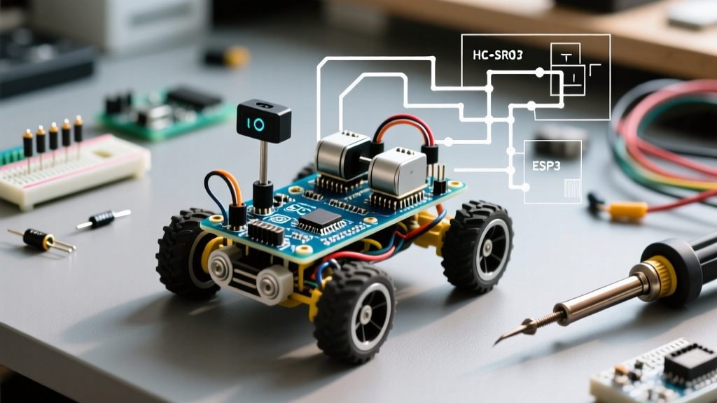
For small-batch PCB assembly, the community has developed a 4-axis desktop pick-and-place machine driven by an Arduino Mega 2560 Rev3 ($42.00). This project bridges the gap between manual tweezers work and industrial SMT lines, utilizing 3D printed PLA+ and carbon-fiber-reinforced nylon joints.
Kinematics & Stepper Configuration
The arm utilizes four NEMA 17 stepper motors driven by TMC2209 UART drivers ($6.00 each). The TMC2209’s StallGuard feature enables sensorless homing, eliminating the need for physical limit switches and reducing 3D printed part complexity. When wiring the UART lines, remember to place a 1kΩ resistor between the Arduino’s TX pin and the TMC2209’s RX pin to prevent bus contention and ensure reliable baud-rate communication.
Microcontroller Selection Matrix for 3D Printer Mods
Choosing the right board is critical for Arduino 3D printing projects. Below is a 2026 comparison matrix based on community consensus for specific printer modifications.
| Microcontroller | Approx. Price | Best Application | Key Limitation |
|---|---|---|---|
| Arduino Uno R4 WiFi | $27.50 | Thermal chambers, PID heating | Limited SRAM for complex kinematics |
| Arduino Nano ESP32 | $18.00 | IoT sensors, weight tracking | ADC non-linearity requires software calibration |
| Arduino Mega 2560 | $42.00 | Multi-axis robotic arms, CNC | 5V logic requires level shifters for 3.3V sensors |
| Arduino Portenta H7 | $115.00 | Machine vision, defect detection | Overkill for simple G-code parsing |
Slicer Settings for Functional Arduino Enclosures
When designing enclosures for these projects, dimensional accuracy is paramount. According to extensive testing documented on All3DP, standard FDM printers exhibit a 0.1mm to 0.2mm hole shrinkage due to plastic cooling dynamics.
- Clearance: Always add a 0.2mm XY clearance to holes meant for M3 screws and standoffs.
- Threads: Never 3D print internal threads for structural joints. Instead, print undersized holes and use a standard M3 tap, or design for brass heat-set inserts (e.g., M3x5x4mm). Heat the insert with a soldering iron set to 250°C and press it in slowly for a permanent, high-strength bond.
- Tolerances: For snap-fits, maintain a 0.15mm tolerance gap between mating surfaces in your CAD software before exporting to STL.
Power Delivery and Optoisolation Best Practices
Integrating low-voltage Arduino logic with 24V 3D printer power supplies requires strict isolation. Never share the ground plane directly between high-current stepper lines and sensitive I2C sensor lines without proper filtering.
Expert Tip: Use an LM2596 buck converter to step down the printer’s 24V PSU to 5V for the Arduino. However, to prevent ground loops and voltage spikes from back-EMF, route the 5V power through an ISO7241 digital isolator if you are reading data directly from the printer’s mainboard UART header.
For comprehensive wiring diagrams and community-vetted schematics, repositories on Hackaday remain an invaluable resource for troubleshooting edge-case EMI (Electromagnetic Interference) issues that frequently plague DIY printer mods.
Frequently Asked Questions (FAQ)
Can I power an Arduino directly from a 3D printer’s 5V rail?
It is not recommended. The 5V rail on standard printer mainboards (like the BTT SKR series) is typically sourced from a linear regulator or a small buck converter that may already be near its current limit powering the board’s logic and fans. Adding an Arduino and external sensors can cause brownouts and corrupt SD card writes. Always use a dedicated buck converter wired directly to the 24V input terminals.
Where can I find official pinout diagrams for these builds?
The Arduino Official Documentation provides exhaustive pinout maps, power limits, and I2C address guides for all first-party boards mentioned in this showcase.
What is the best filament for printing gears for the robotic arm?
For low-speed, high-torque gears in desktop pick-and-place arms, Nylon-Carbon Fiber (PA-CF) offers the best wear resistance and dimensional stability. Avoid standard PLA, which will quickly strip under the friction of continuous operation and deform under the heat of stepper motors.