
The Evolution of Arduino Projects for Industrial Telemetry
When engineers and makers search for advanced arduino projects for industrial automation or robotics, the conversation quickly moves beyond simple temperature logging or relay switching. In 2026, the standard for edge computing demands sub-degree orientation tracking, localized sensor fusion, and deterministic polling rates. Relying on raw accelerometer and gyroscope data requires complex Kalman filtering on the host MCU, which consumes valuable clock cycles and introduces latency.
The solution lies in offloading sensor fusion to dedicated System-in-Package (SiP) modules. By combining a high-performance IMU with a dual-core edge processor, you can build an Attitude and Heading Reference System (AHRS) capable of tracking complex 3D motion without burdening your main application logic. This guide details the architecture, hardware selection, and firmware design required to build a professional-grade sensor fusion node.
IMU Selection Matrix: Offloading Sensor Fusion
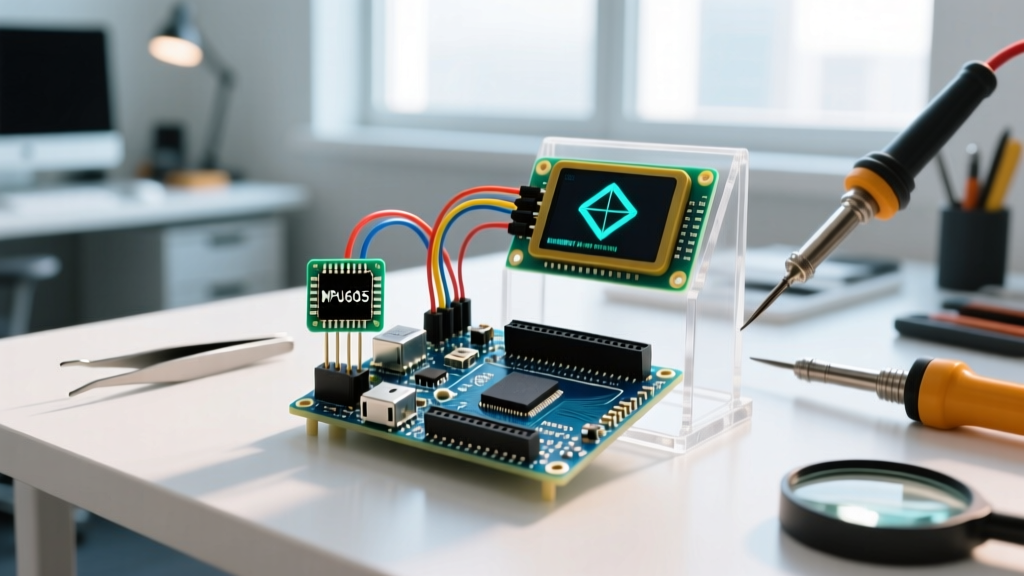
Choosing the right Inertial Measurement Unit (IMU) is the most critical hardware decision in your build. While raw sensors like the MPU6050 are cheap, they lack onboard processing. For advanced builds, we require an IMU with an integrated sensor hub that outputs fused quaternions directly.
| IMU Model | Fusion Engine | Interface | Approx. Price | Best Use Case |
|---|---|---|---|---|
| Bosch BNO055 | On-chip (NDOF) | I2C / SPI | $34.95 | Robotics, AHRS, Drones |
| TDK ICM-20948 | Requires MCU DMP | I2C / SPI | $15.50 | Low-power wearables |
| Bosch BNO086 | On-chip (AR/VR) | I2C / SPI / UART | $42.00 | VR Headsets, Motion Capture |
For this build, we are selecting the Bosch Sensortec BNO055. It integrates a triaxial 14-bit accelerometer, a triaxial 16-bit gyroscope, and a triaxial geomagnetic sensor alongside a 32-bit Cortex-M0 microcontroller. This onboard MCU executes the sensor fusion algorithms, outputting highly stable quaternion data at up to 100Hz.
Hardware Architecture: ESP32-S3 and BNO055 Integration
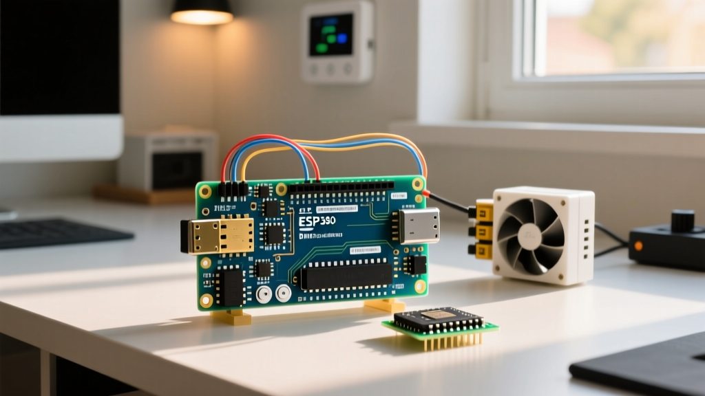
While the classic ATmega328P (Arduino Uno) is a staple for hobbyists, it lacks the RAM and processing architecture required for high-speed data logging and concurrent wireless telemetry. We utilize the Espressif ESP32-S3 (approx. $12.50 for a DevKitC-1 board). The S3 variant features dual-core Xtensa LX7 processors running at 240 MHz, vector instructions for AI acceleration, and native USB, making it the optimal choice for handling high-throughput SPI data while simultaneously managing a WiFi/ESP-NOW mesh network.
Overcoming I2C Capacitance Limits with SPI
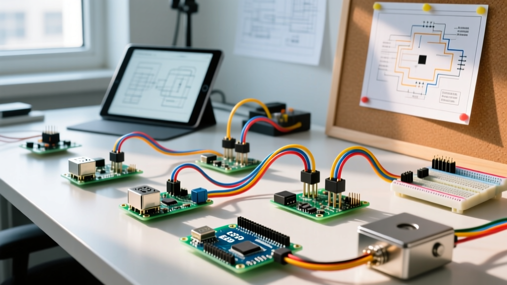
A common failure mode in advanced sensor builds is I2C bus instability. The I2C specification limits total bus capacitance to 400pF. In a robotic chassis with long wiring harnesses, the parasitic capacitance of the cables ($C_{trace} + C_{wires} + C_{pins}$) easily exceeds this limit, resulting in corrupted data, NACK errors, and locked buses. Furthermore, pulling the lines high quickly enough at 400kHz requires impractically low pull-up resistor values (e.g., 1kΩ), which increases power consumption and noise susceptibility.
The Fix: Bypass I2C entirely and wire the BNO055 via SPI. The BNO055 supports SPI clock speeds up to 10MHz. Wire the SCK to GPIO12, MISO to GPIO13, MOSI to GPIO11, and CS to GPIO10 on the ESP32-S3. Ensure you use a logic level shifter if your specific BNO055 breakout board does not have onboard 3.3V regulation, as the ESP32-S3 is strictly a 3.3V logic device and feeding 5V into its GPIOs will permanently damage the silicon.
FreeRTOS Core Allocation for Deterministic Polling
Polling an IMU inside the standard Arduino loop() function introduces timing jitter, especially if WiFi events or serial printing interrupt the cycle. To guarantee a stable 100Hz sample rate, we leverage the ESP32's FreeRTOS capabilities to pin specific tasks to specific cores.
- Core 0 (Sensor Task): Dedicated exclusively to reading the BNO055 via SPI, parsing the quaternion packets, and pushing the data into a thread-safe FreeRTOS queue. Stack size: 4096 bytes.
- Core 1 (Telemetry Task): Handles WiFi stack operations, UDP packet broadcasting, and SD card logging. Stack size: 8192 bytes.
By using xTaskCreatePinnedToCore, you isolate the time-critical sensor polling from the non-deterministic WiFi interrupts handled by the ESP-IDF background tasks.
Advanced Calibration and NVS Persistence
The most frequent complaint among engineers working with the BNO055 is the requirement to perform a 'figure-8' calibration dance every time the device powers on. The magnetometer requires continuous calibration to compensate for local hard and soft iron distortions.
Pro-Tip: Never force your end-users to recalibrate on every boot. Once the BNO055 reaches a 'Fully Calibrated' state (System Status = 3), read the 22-byte calibration profile array from the sensor's registers and write it to the ESP32's Non-Volatile Storage (NVS) using the
Preferences.hlibrary. On subsequent boots, inject these saved offsets back into the BNO055's calibration registers during the initialization sequence.
This technique reduces boot-to-ready time from 30 seconds of physical manipulation to under 200 milliseconds, a mandatory requirement for deployment in commercial drones or autonomous rovers.
Quaternion Math vs. Euler Angles in Edge Processing
Beginner tutorials often convert IMU data into Euler angles (Pitch, Roll, Yaw) for easy human readability. However, Euler angles suffer from gimbal lock—a mathematical singularity that occurs when pitch approaches ±90 degrees, causing a loss of one degree of freedom and resulting in erratic, unpredictable axis flipping.
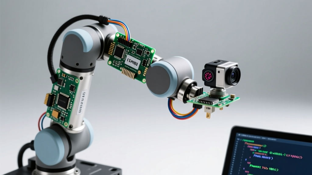
For any advanced Arduino project involving robotic arm kinematics or drone stabilization, you must process the data natively in Quaternions ($w, x, y, z$). Quaternions represent 3D rotations without singularities. If your edge application requires Euler angles for a specific PID controller, perform the conversion locally on the ESP32-S3 using optimized C++ math libraries only at the final output stage, ensuring the internal control loops remain singularity-free.
Real-World Failure Modes and Mitigations
When deploying sensor fusion nodes in the field, theoretical designs meet physical realities. Here are the most common edge cases and how to engineer around them:
- Magnetic Saturation: If your BNO055 is mounted within 5cm of high-current brushless motor ESCs or neodymium magnets, the magnetometer will saturate, destroying the NDOF (Nine Degrees of Freedom) fusion algorithm. Mitigation: Switch the sensor fusion mode to IMUPLUS (6DOF, gyro + accelerometer only) via software, sacrificing absolute magnetic North heading for stable relative orientation.
- Thermal Drift: The BNO055's internal temperature sensor can be read via register 0x34. If the ambient temperature shifts rapidly (e.g., a drone moving from an air-conditioned lab to a 35°C outdoor environment), the gyroscope zero-rate offset will drift. Mitigation: Implement a software thermal compensation curve in your ESP32 firmware based on the datasheet's thermal drift coefficients.
- SPI Bus Contention: If you share the SPI bus with an SD card module for logging, the SD card's initialization sequence can temporarily drop the SPI clock speed to 400kHz, starving the IMU of bandwidth. Mitigation: Use separate SPI buses (the ESP32-S3 supports SPI2 and SPI3) or ensure the SD card library is configured to maintain high-speed SPI transactions post-initialization.
Final Edge Deployment Considerations
Building advanced sensor fusion nodes requires a paradigm shift from simple microcontroller scripting to embedded systems engineering. By pairing the Bosch BNO055 with the ESP32-S3, utilizing SPI to bypass I2C capacitance limits, and leveraging FreeRTOS for deterministic polling, you elevate your build from a hobbyist prototype to a deployable industrial asset. For further reading on sensor calibration methodologies, refer to the Adafruit BNO055 wiring and calibration guide, which provides excellent baseline visualizations for the calibration registers.