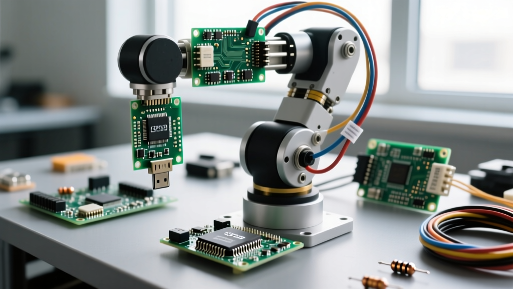

The Concept: Why a Mobile Automation Hub?
Static smart home hubs like the Amazon Echo or Apple HomePod suffer from a fundamental physics limitation: line-of-sight IR constraints and localized sensor blind spots. A roaming home automation hub solves both. By mounting an environmental sensor suite and a high-power IR blaster on a mobile chassis, you create a dynamic node that patrols your home, mapping micro-climates and controlling legacy 'dumb' appliances from any angle.
When architecting a roaming robot arduino hub for home automation, the biggest challenge isn't locomotion—it's electromagnetic interference (EMI) from the drive motors disrupting Wi-Fi telemetry and I2C sensor buses. This guide bypasses generic tutorials and dives straight into the electrical engineering realities of building a robust, MQTT-integrated mobile sentinel using the Arduino Nano 33 IoT.
Bill of Materials (BOM) & 2026 Cost Breakdown
The following components were selected for their 3.3V logic compatibility, low quiescent current draw, and availability. Prices reflect average Q1 2026 market rates from major distributors like Mouser and Digi-Key.
| Component | Model / Part Number | Approx. Price | Purpose |
|---|---|---|---|
| Microcontroller | Arduino Nano 33 IoT (ABX00027) | $45.00 | Brain, Wi-Fi/BLE, 3.3V logic |
| Chassis & Motors | 4WD Acrylic Kit + TT Motors (130 RPM) | $22.00 | Locomotion platform |
| Motor Driver | TB6612FNG Dual H-Bridge | $8.50 | Efficient motor control (low voltage drop) |
| Env. Sensor | Bosch BME280 (I2C) | $12.00 | Temp, Humidity, Pressure mapping |
| IR Blaster LED | Vishay TSAL6200 (940nm) | $0.80 | High-power IR transmission |
| IR Receiver | TSOP38238 (38kHz) | $2.50 | Learning legacy remote codes |
| Power Supply | 2x 18650 Li-ion (Samsung 25R) + Holder | $16.00 | High-discharge mobile power |
| Voltage Regulator | Pololu 3.3V Step-Down (D24V5F3) | $9.00 | Clean logic power rail |
Power Delivery & EMI Mitigation
The most common failure mode in DIY mobile robotics is the 'brownout reset.' TT gear motors have a stall current of roughly 800mA each. If your robot bumps into a wall and all four motors stall simultaneously, the current spike can exceed 3A, causing the battery voltage to sag and resetting the microcontroller.
The Star Grounding Topology
Never daisy-chain your grounds. Use a star grounding topology where the motor ground, logic ground, and sensor ground all meet at a single physical point (usually the negative terminal of the battery pack).
- Motor Noise Suppression: Solder a 0.1µF (100nF) ceramic capacitor directly across the terminals of each TT motor. Additionally, solder a 0.01µF capacitor from each terminal to the motor's metal casing. This shunts high-frequency brush noise to ground before it enters the wiring harness.
- Logic Rail Isolation: Feed the Arduino Nano 33 IoT and the BME280 sensor via a dedicated 3.3V buck converter (like the Pololu D24V5F3). Do not use the onboard linear regulator for high-current peripherals.
- Bulk Capacitance: Place a 470µF electrolytic capacitor in parallel with a 0.1µF ceramic capacitor at the output of the buck converter to handle transient Wi-Fi transmission spikes (which can pull 300mA for microseconds).
High-Power IR Blaster Circuit
The Arduino Nano 33 IoT's SAMD21 GPIO pins are strictly limited to 7mA per pin. The Vishay TSAL6200 IR LED requires 100mA peak current for optimal range. Driving it directly will destroy the microcontroller.
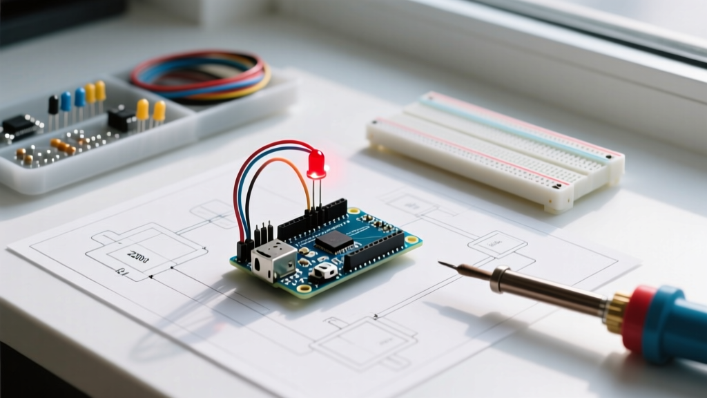
Expert Circuit Design: Use a 2N2222 NPN transistor as a low-side switch. Connect the GPIO pin to the transistor's base via a 1kΩ resistor. Connect the IR LED's cathode to the collector, and the anode to the 3.3V rail via a 10Ω current-limiting resistor. This safely pulses the LED at ~100mA without stressing the SAMD21 silicon.
For decoding incoming signals, the TSOP38238 receiver operates perfectly at 3.3V. Wire its VCC to the 3.3V rail, GND to the common ground, and the OUT pin to Digital Pin 4. According to the SB Projects NEC Protocol Guide, the 38kHz carrier frequency requires precise timing interrupts, which the Arduino IRremote library (v4.4+) handles natively via hardware timers.
Wiring Matrix & Pinout
Below is the definitive wiring map for the Nano 33 IoT. Note that the TB6612FNG is used instead of the older L298N because it utilizes MOSFETs rather than bipolar transistors, resulting in a voltage drop of just 0.5V compared to the L298N's 2.0V drop—crucial for 7.4V battery systems.
| Nano 33 IoT Pin | Target Component | Function |
|---|---|---|
| D4 | TSOP38238 OUT | IR Signal Decode |
| D5 | 2N2222 Base (via 1kΩ) | IR Blaster Transmit |
| D7 / D8 | TB6612FNG PWMA / PWMB | Motor Speed Control (PWM) |
| D9-D12 | TB6612FNG AIN1-BIN2 | Motor Direction Logic |
| A4 (SDA) | BME280 SDA | I2C Data |
| A5 (SCL) | BME280 SCL | I2C Clock |
Firmware: MQTT & Home Assistant Integration
To integrate this robot into a modern smart home, we use MQTT. The robot publishes sensor data and subscribes to IR blast commands. When configuring the Arduino Nano 33 IoT via the official IDE, ensure you install the WiFiNINA, PubSubClient, and IRremote libraries.
Crucial Firmware Adjustments
Standard MQTT buffer sizes are too small for raw IR data arrays. You must increase the buffer size in your setup() function:
client.setBufferSize(1024); // Prevents dropped IR raw arraysFor Home Assistant integration, utilize MQTT Discovery. By publishing a properly formatted JSON payload to the homeassistant/sensor/robot_bme280/config topic, Home Assistant will automatically create the entities without manual YAML configuration. Refer to the Home Assistant MQTT Integration Docs for the exact discovery schema.
Troubleshooting Edge Cases & Failure Modes
Even with perfect wiring, mobile robotics introduces unique edge cases. Here is how to diagnose the three most common issues:
- I2C Bus Lockups: If the BME280 stops reporting data after the robot drives over a carpeted threshold, EMI has likely corrupted the I2C clock line. Solution: Add 4.7kΩ pull-up resistors to both SDA and SCL lines, tied to the 3.3V rail. The Nano 33 IoT has internal pull-ups, but they are too weak for noisy environments.
- Wi-Fi Disconnects During Motor Spin: The TB6612FNG generates switching noise that couples into the Nano's onboard 2.4GHz antenna. Solution: Slide ferrite beads onto the motor wires as close to the TB6612FNG as possible, and ensure the antenna overhangs the edge of the acrylic chassis.
- IR Signal Clipping: If the robot successfully learns a remote code but fails to trigger the TV, the transmit current is too low. Solution: Verify the 10Ω current-limiting resistor on the TSAL6200. If using a 3.3V logic rail, you may need to drop the resistor to 4.7Ω to achieve the necessary 100mA peak forward current.
Final Deployment Strategy
For true home automation, do not rely on manual driving. Write a simple patrol script that uses the WiFiNINA library to check RSSI (signal strength) as a proxy for distance from your router, creating a boundary fence. Combine this with a scheduled Home Assistant automation that triggers the robot to patrol the living room at 18:00, reading the ambient temperature and adjusting your smart thermostat via MQTT based on the room's actual micro-climate, rather than the static hallway sensor.