
Why Move Beyond Serial Debugging?
For most beginners in embedded systems, the Arduino IDE and Serial.println() are the default tools for troubleshooting. While serial output is excellent for basic logging, it fundamentally alters the timing of your program, cannot pause execution, and offers zero visibility into CPU registers or raw memory states. When your project scales to complex state machines, RTOS tasks, or interrupt-driven sensor fusion, serial debugging becomes a severe bottleneck.
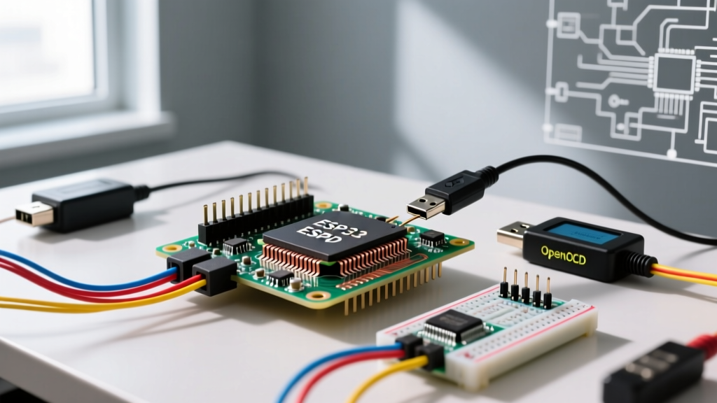
This is where porting Arduino project to OpenOCD (Open On-Chip Debugger) becomes a critical skill. OpenOCD acts as a bridge between your microcontroller's hardware debug interface (JTAG or SWD) and a GDB (GNU Debugger) server. By making this transition, you gain the ability to set hardware breakpoints, step through code line-by-line, inspect memory addresses in real-time, and profile execution cycles without modifying your source code with print statements.
Hardware Probes: What You Need in 2026
OpenOCD requires a hardware debug probe to translate USB commands from your PC into the low-level SWD (Serial Wire Debug) or JTAG signals your microcontroller understands. Below is a comparison of the most reliable probes available for DIY and professional bench use today.
| Debug Probe | Protocol | Target Compatibility | Approx. Cost (2026) | Best For |
|---|---|---|---|---|
| ST-Link V2 (Clone) | SWD / JTAG | STM32 Family | $3 - $6 | Budget STM32 Blue Pill projects |
| Segger J-Link EDU Mini | SWD / JTAG | ARM Cortex-M (Broad) | $18 - $22 | Reliable ARM debugging, nRF52, RP2040 |
| Espressif ESP-Prog | JTAG | ESP32, ESP32-S3, ESP32-C3 | $12 - $15 | Xtensa and RISC-V Espressif chips |
| Raspberry Pi Pico (Picoprobe) | SWD | RP2040, STM32, nRF52 | $4 - $5 | CMSIS-DAP standard, multi-target |
Expert Note: Avoid the ultra-cheap $2 CH552-based clones found on AliExpress if you are debugging high-speed RTOS applications. They frequently drop packets at SWD clock speeds above 4 MHz, leading to phantom GDB disconnects.
Step 1: Transitioning to PlatformIO
The standard Arduino IDE (even the newer 2.x versions) has limited, often clunky support for custom OpenOCD configurations and GDB server management. To properly port your project, you should migrate your build environment to PlatformIO within Visual Studio Code. PlatformIO automatically downloads the correct toolchains, handles the OpenOCD server lifecycle, and integrates the GDB frontend into the VS Code UI.
The platformio.ini Configuration
When porting an existing STM32 Arduino sketch to PlatformIO, your platformio.ini file must explicitly define the debug tool. Here is a production-ready configuration for an STM32F103C8T6 (Blue Pill) using an ST-Link:
[env:bluepill_f103c8]
platform = ststm32
board = bluepill_f103c8
framework = arduino
debug_tool = stlink
upload_protocol = stlink
build_flags = -Og -g3 -ggdb
Critical Build Flags: Notice the -Og -g3 -ggdb flags. By default, release builds optimize code (-Os), which reorders instructions and strips debug symbols. -Og enables optimizations that do not interfere with debugging, while -g3 includes macro definitions in the debug info, allowing you to inspect #define constants in the GDB watch window.
Step 2: SWD Wiring and Hardware Edge Cases
Unlike JTAG, which requires up to 5 data pins, ARM's Serial Wire Debug (SWD) multiplexes data and clock signals, requiring only two data wires plus power. Proper wiring is where 90% of beginners fail when porting their project.
- SWDIO (Serial Wire Data I/O): Connect to the target's PA13 pin (on STM32). This is a bidirectional data line.
- SWCLK (Serial Wire Clock): Connect to the target's PA14 pin. This is the clock signal driven by the probe.
- GND: A common ground reference is mandatory. Without it, the probe will read floating logic levels and fail initialization.
- 3.3V (VCC): Edge Case Warning: Most modern MCUs operate at 3.3V logic. Connecting a 5V probe signal to an STM32F1 or ESP32 will permanently damage the silicon. If your probe does not auto-sense VCC, ensure you are using a logic-level shifter or a 3.3V-native probe.
What about NRST (Reset)? While SWD can technically connect to a running chip, if your Arduino code immediately puts the MCU to sleep or remaps the SWD pins (PA13/PA14) to GPIOs upon boot, OpenOCD will fail to attach. Wiring the NRST pin allows OpenOCD to perform a "connect-under-reset" sequence, halting the CPU before your setup() function can disable the debug port.
Step 3: OpenOCD Configuration Files
OpenOCD relies on a two-part configuration system: the Interface (your probe) and the Target (your microcontroller). When using PlatformIO, these are often abstracted away. However, if you are invoking OpenOCD manually via the terminal for custom flash memory unlocking, you must write an openocd.cfg file.
# openocd.cfg
source [find interface/stlink.cfg]
transport select hla_swd
source [find target/stm32f1x.cfg]
adapter speed 4000
The adapter speed 4000 command sets the SWD clock to 4 MHz. If you experience intermittent connection timeouts on long jumper wires, drop this value to 1000 (1 MHz) to improve signal integrity over unshielded cables.
The ESP32 Exception: Espressif's Custom Fork
Important Architecture Note: Mainline OpenOCD primarily supports ARM Cortex-M and Cortex-A architectures. It does not natively support the Xtensa (ESP32, ESP32-S3) or RISC-V (ESP32-C3, ESP32-C6) architectures used by Espressif.
If your Arduino project uses an ESP32, you cannot use the standard OpenOCD package. Espressif maintains a specialized fork called openocd-esp32. When porting an ESP32 project, PlatformIO handles this fork automatically if you set debug_tool = esp-prog in your environment. Furthermore, the ESP32 requires JTAG (not SWD), meaning you must wire TDI, TDO, TCK, TMS, and TRST pins, usually mapped to GPIO12-GPIO15 on the original ESP32 chip.
Troubleshooting Common Failure Modes
When porting your first project, you will inevitably hit roadblocks. Here are the exact solutions to the most common OpenOCD errors.
1. Linux USB Permission Errors (LIBUSB_ERROR_ACCESS)
The Error: Error: open failed or libusb_open() failed with LIBUSB_ERROR_ACCESS.
The Cause: Linux restricts raw USB access to non-root users. Your user account lacks permission to talk to the ST-Link or J-Link USB device.
The Fix: You must install udev rules. For an ST-Link, create a file at /etc/udev/rules.d/99-stlink.rules and add the following line:
SUBSYSTEM=="usb", ATTR{idVendor}=="0483", ATTR{idProduct}=="3748", MODE="0666"After saving, reload the rules with sudo udevadm control --reload-rules && sudo udevadm trigger, then unplug and replug your probe.
2. UNEXPECTED idcode Errors
The Error: Warn : UNEXPECTED idcode: 0x2ba01477
The Cause: OpenOCD successfully connected to the SWD bus, but the silicon ID it read does not match the target configuration file you provided. This usually happens when you configure target/stm32f1x.cfg but are actually connected to an STM32F4 or a clone chip with a different CoreSight ROM table.
The Fix: Verify your exact MCU part number. If using a clone chip (like the CKS32F103), you may need to add set CPUTAPID 0x2ba01477 before sourcing the target config file to force OpenOCD to accept the non-standard ID.
3. GDB Connection Timeouts
The Error: Remote communication error. Target disconnected.: Connection reset by peer.
The Cause: The GDB server crashed because the target MCU is in a low-power sleep mode (e.g., STM32 Stop/Standby) and the SWD clock is disabled.
The Fix: Wire the NRST pin and enable connect-under-reset in your PlatformIO debug settings by adding debug_server = ... -c "reset_config srst_only srst_nogate connect_assert_srst" to your configuration.
Summary
Porting an Arduino project to OpenOCD transforms your development workflow from guesswork to precision engineering. By investing in a reliable SWD/JTAG probe, migrating to PlatformIO, and understanding the nuances of target configuration and hardware wiring, you unlock professional-grade debugging capabilities. For further reading on the underlying protocols, refer to the official OpenOCD documentation and your specific microcontroller's reference manual.