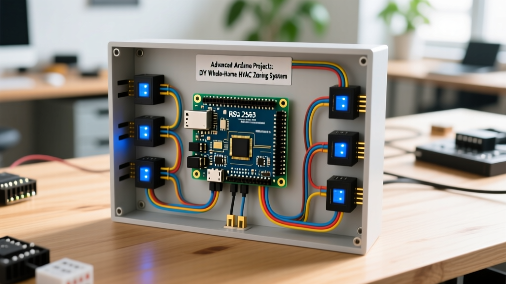

When most makers think of advanced Arduino projects, they envision complex robotics or high-speed data logging. However, the true test of embedded engineering is integrating low-voltage microcontroller logic with high-reliability, high-torque building infrastructure. A whole-home HVAC zoning system represents the pinnacle of DIY home automation. It requires managing differential communication protocols, 24VAC actuator control, real-time environmental telemetry, and critical fail-safes to prevent catastrophic equipment damage.
According to the U.S. Department of Energy, poorly designed duct systems and single-zone thermostats can waste up to 20% of conditioned air. By building a custom multi-zone controller, you can dynamically route airflow only to occupied spaces, drastically improving efficiency and comfort. This guide details how to architect, wire, and program a robust 4-zone HVAC system using the Arduino ecosystem.
System Architecture: The Master-Slave Topology
Running 5V I2C or SPI sensor wires through walls over distances greater than 2 meters is a recipe for signal degradation and data corruption. For a whole-home deployment, we utilize an RS-485 differential signaling network running the Modbus RTU protocol. This allows for cable runs up to 1,200 meters with high immunity to electromagnetic interference (EMI) from nearby AC mains wiring.
- Master Node: Arduino Mega 2560 Rev3. Acts as the central brain, polling zone nodes, calculating thermal demand, and triggering the main furnace/AC relays.
- Zone Nodes (Slaves): Arduino Nano Every (one per zone). Reads local temperature/humidity sensors and controls the local motorized duct damper.
- Communication Bus: RS-485 transceivers connected via Cat5e twisted-pair cable.
Bill of Materials (BOM) & Component Selection
Selecting the right actuators is where most DIY HVAC projects fail. Standard 5V DC servos lack the torque to move metal dampers against static pressure and will burn out. You must use industrial-grade 24VAC actuators with spring-return mechanisms.
| Component | Model / Specification | Est. Cost (2026) | Purpose |
|---|---|---|---|
| Master MCU | Arduino Mega 2560 Rev3 | $28.00 | Central logic, Modbus Master, Relay control |
| Zone MCU | Arduino Nano Every (x4) | $18.00 ea. | Zone logic, Modbus Slave, Damper PWM |
| Transceivers | MAX485 RS-485 Modules (x5) | $2.50 ea. | Differential serial communication |
| Damper Actuators | Belimo LF24-SR (24VAC, Spring Return) | $115.00 ea. | Modulates duct airflow, fails open on power loss |
| Zone Sensors | Sensirion SHT40 (I2C) | $8.00 ea. | High-accuracy temperature and humidity reading |
| Static Pressure Gauge | Dwyer 2000-60Pa Magnehelic | $85.00 | Monitors plenum pressure for bypass damper control |
Wiring the RS-485 Network for Multi-Room Reliability
The physical layer of your network dictates its reliability. The Modbus Organization specifies strict guidelines for RS-485 physical implementations to prevent signal reflection and data collisions.
Cable Selection and Termination
Use standard Cat5e ethernet cable. Dedicate one twisted pair (e.g., Orange/Orange-White) for the RS-485 A and B data lines, and another pair for the DC ground reference. Do not rely on the building's earth ground for your RS-485 common reference; always run a dedicated ground wire back to the master node's power supply.
Critical Engineering Rule: You must install 120-ohm termination resistors across the A and B lines at the extreme first and last nodes of your RS-485 daisy chain. Without these, high-frequency signal reflections will cause intermittent Modbus CRC checksum failures, leading to phantom zone commands and erratic damper behavior.
Biasing the Network
When the RS-485 bus is idle, the differential voltage between A and B can float, causing the receiver to interpret electrical noise as valid data bytes. To prevent this, install a bias network at the Master node:
- Pull the 'A' line HIGH with a 560-ohm resistor to +5V.
- Pull the 'B' line LOW with a 560-ohm resistor to GND.
Motorized Damper Calibration & Static Pressure Management
The Belimo LF24-SR is a proportional actuator. It accepts a 2-10VDC control signal from the Arduino Nano (via a simple PWM-to-analog low-pass filter or a dedicated DAC like the MCP4725) to position the damper blade anywhere from 0% (closed) to 100% (open). More importantly, it features a mechanical spring return. If the 24VAC power drops, the spring forces the damper open. This is a vital fail-safe: if your Arduino crashes during a winter heating cycle, the dampers default to open, ensuring hot air continues to flow and preventing your furnace heat exchanger from overheating or your AC evaporator coil from freezing into a block of ice.
The Hidden Killer: Static Pressure Spikes
According to EPA ENERGY STAR guidelines, restricting airflow in HVAC systems damages equipment. If your Arduino logic decides to close 3 out of 4 zone dampers simultaneously, the static pressure in the main supply plenum will spike dramatically. This can blow apart flex-duct joints, stall the blower motor, and cause severe noise.
The Solution: You must install a barometric bypass damper in your ductwork that routes excess air from the supply plenum back into the return plenum. For advanced control, wire a Dwyer Magnehelic differential pressure gauge to an analog input on the Arduino Mega. Set a threshold (typically 0.5 to 0.8 inches of water column, depending on your blower specs). If the Mega detects pressure exceeding this threshold, it overrides the zone logic and forces the bypass damper open to relieve the system.
Programming the Modbus RTU Logic
For the software stack, utilize the official ArduinoRS485 and ArduinoModbus libraries. The Master node operates on a strict polling loop, while the Slaves operate purely on interrupt-driven serial events.
Register Mapping Strategy
Do not send raw floating-point temperature values over Modbus, as it requires complex 32-bit register pairing. Instead, multiply the temperature by 10 and send it as a 16-bit integer (e.g., 72.5°F becomes 725).
- Holding Register 0: Zone Target Temperature (Integer)
- Holding Register 1: Damper Position Override (0-100%)
- Input Register 0: Current Zone Temperature (Integer)
- Input Register 1: Current Zone Humidity (Integer)
- Input Register 2: Node Status / Watchdog Timer
Implementing a Watchdog Fail-Safe
In advanced Arduino projects, you must assume the code will eventually hang due to memory leaks or I2C bus lockups. Implement a hardware watchdog timer (WDT) on every Nano zone node. If the Master node fails to poll a specific zone for more than 120 seconds, the zone node's WDT triggers a soft reset. If the RS-485 bus itself goes down, the Nano's logic should default the local Belimo actuator to a 50% open position to maintain baseline ventilation.
Real-World Troubleshooting Matrix
When deploying this system in a real home, you will encounter edge cases that don't appear on the workbench. Use this matrix to diagnose field issues:
| Symptom | Root Cause | Engineering Fix |
|---|---|---|
| Random Modbus CRC Errors on Zone 3 | EMI from nearby 120V/240V AC mains wiring coupling into the RS-485 pair. | Ensure Cat5e is routed at least 12 inches away from AC mains. Verify the 120-ohm termination resistor is properly soldered. |
| Furnace short-cycles; high-limit switch trips | Too many dampers closed; static pressure spiked, reducing airflow across the heat exchanger. | Recalibrate the Dwyer Magnehelic bypass threshold. Ensure the Master MCU enforces a 'minimum open zones' logic rule. |
| SHT40 Sensor reads 10°F higher than actual | Thermal bleeding from the Arduino Nano's onboard voltage regulator heating the I2C sensor. | Mount the SHT40 on a 4-pin JST extension cable, physically separating it from the Nano PCB by at least 6 inches. |
| Damper hums loudly but doesn't move | Insufficient VA (Volt-Amps) on the 24VAC transformer; voltage sag under load. | Upgrade the HVAC control transformer from 40VA to 75VA to handle the inrush current of multiple Belimo actuators starting simultaneously. |
Conclusion: Bridging the Gap to Professional Automation
Building a whole-home HVAC zoning system elevates your skills from simple breadboard prototyping to systems-level engineering. By respecting the physical constraints of RS-485 communication, understanding the thermodynamic realities of static pressure, and implementing robust hardware fail-safes, you create a system that doesn't just work on a desk—it survives the harsh, electrically noisy, and mechanically demanding environment of a real home. This is the true definition of advanced Arduino projects: creating infrastructure that is invisible, reliable, and fundamentally improves daily life.