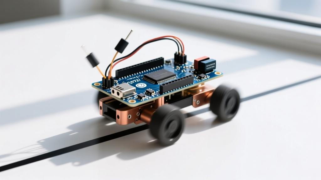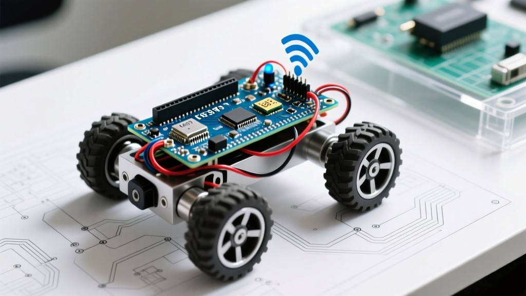

Why Build an IoT-Connected Arduino Robot?
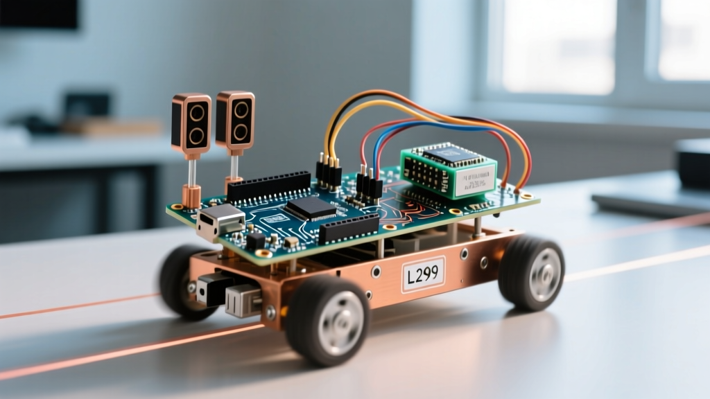
Learning how to make an Arduino-based robot is a rite of passage for electronics hobbyists, but most tutorials stop at standalone line-followers or ultrasonic obstacle avoiders. In 2026, the real value lies in connectivity. By transforming a standard 2WD rover into an IoT connected device, you unlock remote telemetry, over-the-air (OTA) updates, and low-latency control via MQTT from anywhere in the world.
This guide bypasses basic blink-LED tutorials and dives straight into building a robust, WiFi-enabled IoT rover using the Arduino Uno R4 WiFi. We will cover motor driver isolation, MQTT topic architecture, and the critical EMI (Electromagnetic Interference) mitigation steps that most beginners miss.
Hardware Bill of Materials (2026 Pricing)
To ensure reliable IoT connectivity and sufficient torque, we are avoiding cheap 4xAA battery holders and outdated L293D drivers. Here is the exact BOM for a professional-grade hobbyist build.
| Component | Specific Model / Part | Est. Price | Purpose |
|---|---|---|---|
| Microcontroller | Arduino Uno R4 WiFi (Renesas RA4M1 + ESP32-S3) | $27.50 | Core logic and WiFi/MQTT connectivity |
| Motor Driver | L298N Dual H-Bridge Module | $6.00 | High-current motor switching |
| Chassis & Motors | 2WD Acrylic Chassis w/ 3-6V TT Gearmotors | $14.00 | Locomotion platform |
| Power Supply | 2S 7.4V 18650 Li-ion Pack (e.g., Zeee 2200mAh) | $18.00 | High-discharge power for motors |
| Logic Regulator | Hobbywing 5V/3A UBEC | $9.50 | Isolated, noise-free 5V for the MCU |
| Telemetry Sensor | Bosch BME280 (I2C) | $5.50 | Environmental data logging |
Total Estimated Cost: ~$80.50
Pinout and Wiring Matrix
Proper wiring is critical when mixing high-current DC motors with sensitive 2.4GHz WiFi antennas. Use a star-ground topology where all ground wires meet at a single terminal block, rather than daisy-chaining grounds through the Arduino headers.
Motor Driver to Uno R4 WiFi
- ENA (PWM) -> Pin D5
- IN1 -> Pin D4
- IN2 -> Pin D7
- ENB (PWM) -> Pin D6
- IN3 -> Pin D8
- IN4 -> Pin D9
- GND -> Common Ground Bus
BME280 I2C Telemetry Sensor
- VCC -> 3.3V (Do not use 5V, the BME280 is strictly 3.3V logic)
- GND -> Common Ground Bus
- SCL -> A5
- SDA -> A4
The Hidden Killer: Motor EMI and WiFi Dropouts
If you have ever built a WiFi robot and noticed that the connection drops the exact moment the motors start spinning, you have encountered EMI. Brushed DC TT gearmotors use carbon brushes that create broadband RF noise. This noise travels back through the power rails and radiates directly into the ESP32-S3 antenna on the Uno R4 WiFi, causing packet loss or hard watchdog resets.
Expert Fix: Never power the Arduino logic directly from the same 7.4V LiPo rail feeding the L298N motor driver without isolation. Use a UBEC (Universal Battery Elimination Circuit) to step down the battery voltage to a clean 5V for the Arduino's VIN pin. Additionally, solder 100nF ceramic capacitors directly across the positive and negative terminals of each physical motor.
By isolating the logic power and suppressing noise at the source, your MQTT keep-alive packets will maintain sub-50ms latency even during aggressive acceleration.
MQTT Topic Architecture
For IoT control, we use the MQTT protocol. It is lightweight and ideal for mobile networks. You can host your own broker using Eclipse Mosquitto on a local Raspberry Pi, or use a cloud broker like HiveMQ for WAN access.
Structure your topics to allow for future fleet scaling:
robot/rover1/cmd(Subscribe): Receives JSON movement commands.robot/rover1/telemetry(Publish): Sends BME280 sensor data and battery voltage.robot/rover1/status(Publish): Retained message for online/offline state.
A typical command payload looks like this:{"action": "forward", "speed": 220, "duration": 500}
Firmware Logic and WiFiS3 Implementation
The Arduino Uno R4 WiFi utilizes the WiFiS3 library, which is a significant upgrade over the older WiFiNINA architecture. When writing your firmware, avoid using delay() for motor timing, as this blocks the ESP32-S3 from processing incoming WiFi stack events.
Instead, use a non-blocking state machine. Here is the logical flow for the main loop:
- Check WiFi Status: If disconnected, attempt reconnection with an exponential backoff delay (1s, 2s, 4s, 8s) to prevent flooding your router.
- Poll MQTT Client: Call
client.poll()to process incoming messages on thecmdtopic. - Parse JSON: Use the
ArduinoJsonlibrary to extract speed and direction vectors. - Actuate Motors: Map the speed (0-255) to the PWM pins via
analogWrite(). - Telemetry Timer: Every 2000ms, read the BME280 and battery voltage via a voltage divider, serialize to JSON, and publish to the
telemetrytopic.
Troubleshooting Edge Cases
1. Brownout Detector Triggered on Motor Start
Symptom: The robot connects to WiFi, but when a 'forward' command is received, the serial monitor prints Brownout detector was triggered and the board reboots.
Cause: The TT motors draw up to 800mA each at stall. If your battery has a high internal resistance or you are using a standard 9V alkaline battery, the voltage sags below the ESP32-S3's 2.7V minimum operating threshold.
Solution: Switch to a high C-rating 2S LiPo battery (minimum 1500mAh) and ensure your wiring uses at least 18 AWG silicone wire for the main power distribution.
2. MQTT Connection Timeout on Public Networks
Symptom: The robot connects to your home WiFi but fails to authenticate with a cloud MQTT broker, timing out after 10 seconds.
Cause: Many public cloud brokers require TLS/SSL encryption on port 8883, but the default ArduinoMqttClient examples often use unencrypted port 1883, which may be blocked by your ISP or router firewall.
Solution: Use the WiFiSSLClient class instead of WiFiClient when initializing your MQTT client, and ensure your broker supports Let's Encrypt certificates which the ESP32-S3 can validate.
3. I2C BME280 Returning NaN (Not a Number)
Symptom: Telemetry publishes successfully, but temperature and humidity values show as NaN.
Cause: The I2C pull-up resistors on cheap BME280 breakout boards are often 10kΩ, which is too weak for the 3.3V logic level of the Uno R4 when long wires are used, causing signal degradation from motor EMI.
Solution: Solder additional 4.7kΩ pull-up resistors to the SDA and SCL lines, and keep the I2C wire length under 15cm.
Next Steps: Dashboard Integration
Once your firmware is stable and publishing telemetry, connect your MQTT broker to a Node-RED instance or an IoT platform like Blynk. You can map the robot/rover1/telemetry JSON keys to real-time gauges, allowing you to monitor the robot's internal temperature and battery degradation as it navigates your environment. Building an IoT robot is not just about making something move; it is about creating a reliable, observable data node on wheels.