
The Foundational Rite of Passage: Closed-Loop Robotics
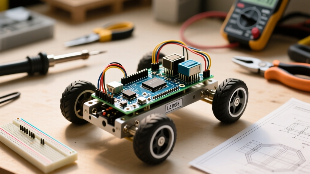
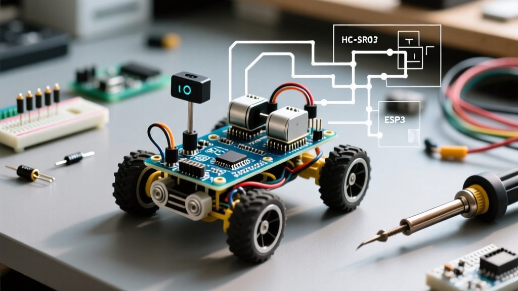
Building a line following robot with Arduino is the ultimate gateway into embedded systems and closed-loop control theory. Unlike simple remote-controlled cars that rely on open-loop human input, a line follower must perceive its environment, calculate an error margin, and actuate motors autonomously in real-time. In this 2026 beginner guide, we bypass the outdated, jittery 'bang-bang' control logic found in legacy tutorials and implement a Proportional (P) Controller. This ensures your robot glides smoothly along the track rather than violently oscillating across the tape.
Bill of Materials (BOM) & 2026 Component Selection
Component selection dictates your robot's performance ceiling. While the classic Arduino Uno R3 is still ubiquitous, upgrading to the Arduino Uno R4 Minima is highly recommended for this project. The R4 features a 14-bit Analog-to-Digital Converter (ADC), yielding 16,384 discrete values compared to the R3's 10-bit (1,024 values). This massive increase in analog resolution allows your infrared sensors to detect subtle gradients in tape reflectivity, enabling sharper cornering.
| Component | Specific Model / Recommendation | Est. Cost (USD) |
|---|---|---|
| Microcontroller | Arduino Uno R4 Minima (or R3 Clone) | $18.00 / $12.00 |
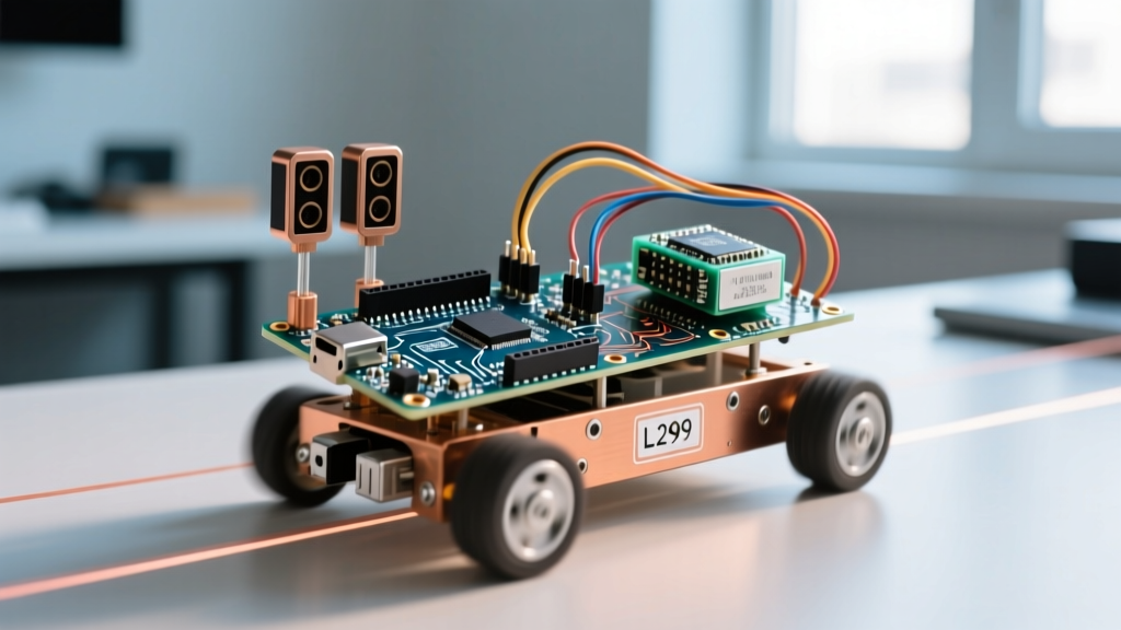
| Motor Driver | L298N Dual H-Bridge Module | $4.50 |
| IR Sensors | TCRT5000 Reflective Optical Sensor (x3) | $6.00 ($2 ea) |
| Motors & Wheels | TT Gear Motors (1:48 ratio) + Rubber Wheels | $8.00 |
| Chassis | Acrylic 2WD Baseplate with Caster Wheel | $5.00 |
| Power Supply | 2x 18650 Li-ion Cells (e.g., Samsung 25R) + Holder | $14.00 |
Understanding the Physics: Reflectance and IR Gradients
The TCRT5000 sensor module houses an infrared LED and a phototransistor. The LED emits IR light at a wavelength of roughly 950nm onto the floor. White surfaces reflect this light back into the phototransistor, lowering its internal resistance and outputting a higher voltage. Black electrical tape absorbs the IR spectrum, resulting in low reflectance and a lower output voltage.
Expert Insight: Do not use the digital output (D0) pin on cheap TCRT5000 modules. The onboard potentiometer and LM393 comparator introduce hysteresis and binary 'jitter' at the tape edge. Always wire the Analog Output (A0) pin directly to your Arduino's ADC pins to capture the raw voltage gradient. For deeper sensor theory, refer to the Pololu Reflectance Sensor Guide.
Step-by-Step Wiring & Power Distribution
The most common failure mode for beginners is attempting to power TT gear motors directly from the Arduino's 5V rail. Motors induce massive back-EMF voltage spikes and draw stall currents exceeding 800mA, which will instantly fry your microcontroller's linear regulator. We use the L298N H-Bridge to isolate the high-current motor loop from the low-current logic loop.
Pinout Mapping Table
| Module Pin | Arduino Uno R4 / R3 Pin | Function |
|---|---|---|
| L298N ENA | D5 (PWM) | Left Motor Speed Control |
| L298N IN1 | D4 | Left Motor Direction A |
| L298N IN2 | D7 | Left Motor Direction B |
| L298N ENB | D6 (PWM) | Right Motor Speed Control |
| L298N IN3 | D8 | Right Motor Direction A |
| L298N IN4 | D9 | Right Motor Direction B |
| Left TCRT5000 A0 | A0 | Left Sensor Analog Read |
| Center TCRT5000 A0 | A1 | Center Sensor Analog Read |
| Right TCRT5000 A0 | A2 | Right Sensor Analog Read |
Note on L298N Power: Connect your 2S Li-ion battery pack (approx. 7.4V - 8.4V) to the L298N's 12V and GND screw terminals. Leave the 5V jumper cap ON the L298N board; this routes the board's internal 5V regulator output to the '5V' pin, which you will then connect to the Arduino's '5V' or 'VIN' pin to power the logic safely.
The Arduino C++ Code: Implementing Proportional Control
Instead of basic if/else statements, we use a Proportional (P) control algorithm. The robot calculates the 'error'—the distance between the robot's center and the line. The motor speed adjustment is directly proportional to this error. For a comprehensive breakdown of control loops, review the Wikipedia entry on PID Controllers.
// Pin Definitions
const int LEFT_SENSOR = A0;
const int CENTER_SENSOR = A1;
const int RIGHT_SENSOR = A2;

const int ENA = 5;  // Left Motor PWM
const int IN1 = 4;  // Left Motor Dir
const int IN2 = 7;
const int ENB = 6;  // Right Motor PWM
const int IN3 = 8;  // Right Motor Dir
const int IN4 = 9;

// Control Variables
int baseSpeed = 120;   // Base PWM value (0-255)
int Kp = 15;           // Proportional Constant (Requires tuning)
int setPoint = 512;    // Target analog value (calibrate for your tape)

void setup() {
  pinMode(ENA, OUTPUT);
  pinMode(ENB, OUTPUT);
  pinMode(IN1, OUTPUT);
  pinMode(IN2, OUTPUT);
  pinMode(IN3, OUTPUT);
  pinMode(IN4, OUTPUT);
  Serial.begin(9600);

  // Set initial forward direction
  digitalWrite(IN1, HIGH);
  digitalWrite(IN2, LOW);
  digitalWrite(IN3, HIGH);
  digitalWrite(IN4, LOW);
}

void loop() {
  int centerVal = analogRead(CENTER_SENSOR);
  int leftVal = analogRead(LEFT_SENSOR);
  int rightVal = analogRead(RIGHT_SENSOR);

  // Calculate weighted position error
  // Center sensor dictates primary tracking, edges provide sharp turn cues
  int error = setPoint - centerVal;

  // Add aggressive bias if line is completely lost on one side
  if (leftVal > setPoint + 100) error += 200;
  if (rightVal > setPoint + 100) error -= 200;

  // Proportional Control Math
  int motorAdjust = error * Kp;

  int leftMotorSpeed = baseSpeed + motorAdjust;
  int rightMotorSpeed = baseSpeed - motorAdjust;

  // Constrain PWM values to valid 0-255 range
  leftMotorSpeed = constrain(leftMotorSpeed, 0, 255);
  rightMotorSpeed = constrain(rightMotorSpeed, 0, 255);

  analogWrite(ENA, leftMotorSpeed);
  analogWrite(ENB, rightMotorSpeed);
}
Calibration and Real-World Troubleshooting
Hardware assembly is only 40% of the battle. The remaining 60% is environmental calibration. Use the Arduino Serial Monitor to read raw sensor values before taping down your track.
Common Failure Modes & Solutions
- The Robot Spins in Circles on Power-Up: Your motor polarity is inverted. Swap the wires for the offending motor on the L298N OUT1/OUT2 or OUT3/OUT4 terminals. Alternatively, invert the logic in the
setup()function. - Oscillation (Zig-Zagging) on Straightaways: Your
Kpvalue is too high. The system is overcorrecting. ReduceKpfrom 15 down to 5 or 8 until the motion dampens into a smooth glide. - Robot Drifts Off the Line on Turns: The
baseSpeedis too high for the physical traction limit of your TT motors. Lower thebaseSpeedvariable to 90 to allow the proportional error term enough overhead to brake the inside wheel effectively. - Sensors Read Constant High/Low: Ambient sunlight contains massive amounts of infrared noise. If testing outdoors or near a window, the sun will blind the TCRT5000 phototransistors. Build a small shroud out of black heat-shrink tubing or electrical tape around the sensors to block ambient IR.
Next Steps: Upgrading to Full PID
Once you have mastered this Proportional build, your next upgrade path is implementing the Integral and Derivative terms (PID). The Derivative term will predict the slope of the approaching curve, allowing the robot to pre-emptively brake before sharp 90-degree corners. Mastering this line following robot with Arduino lays the exact mathematical groundwork used in modern autonomous vehicle lane-keeping systems.