
Beyond the Basic 2-Sensor Bot: The Community Showcase
If you have ever built a beginner robotics kit, you are likely familiar with the classic two-sensor, L298N motor driver setup. While it is an excellent introduction to microcontrollers, it fundamentally limits your robot to sluggish speeds of around 0.3 to 0.5 meters per second. When the track curves sharply, the binary 'left-or-right' logic causes aggressive skidding and overshooting.
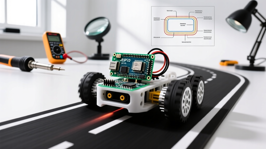
In this month's Community Project Showcase, we are featuring the 'ApexTrack V2'—a high-speed line following robot Arduino build submitted by community member Alex R. Capable of navigating complex tracks at speeds exceeding 1.8 m/s, this project abandons basic bang-bang control in favor of a multi-sensor array and a finely tuned PID (Proportional-Integral-Derivative) algorithm. Below, we break down the exact hardware, wiring, and mathematical tuning strategies that make this build a masterclass in embedded control systems.
Project Spotlight: ApexTrack V2 Bill of Materials
To achieve high-speed stability, every component must minimize latency and maximize power efficiency. As of 2026, the cost of high-performance micro-robotics components has dropped significantly, making this build highly accessible.
| Component | Specific Model / Spec | Est. Cost (2026) | Purpose & Advantage |
|---|---|---|---|
| Microcontroller | Arduino Nano Every (ATmega4809) | $11.00 | 5V logic compatibility, faster clock speed, and more memory than the classic Nano. |
| Sensor Array | Pololu QTR-8RC (8-Channel Reflectance) | $12.50 | Uses RC timing instead of ADC, allowing for 400Hz+ polling rates. |
| Motor Driver | TB6612FNG Dual Motor Driver Carrier | $6.50 | MOSFET-based; drops only ~0.5V compared to the L298N's 2V drop. |
| Motors | Pololu 30:1 Micro Metal Gearmotors (HPCB 6V) | $24.00 (pair) | High torque at low RPM, essential for rapid acceleration out of corners. |
| Chassis | Custom 3D Printed PETG (2mm wall thickness) | $8.00 (filament) | Lightweight, rigid, and allows precise sensor height mounting (3mm off ground). |
| Power | 2S LiPo Battery (7.4V, 800mAh, 30C) | $18.00 | High discharge rate prevents voltage sag during rapid motor direction changes. |
Hardware Deep Dive: Why We Ditch the L298N
The most common failure point in intermediate line following robot Arduino projects is the motor driver. The ubiquitous L298N uses older Bipolar Junction Transistor (BJT) technology. This results in a voltage drop of roughly 1.5V to 2V across the chip. If you supply 7.4V from a LiPo, your motors only see ~5.5V, severely limiting top speed and torque.
The MOSFET Advantage: TB6612FNG
The community build utilizes the TB6612FNG motor driver, which uses MOSFETs. The voltage drop is a mere 0.5V at 1A continuous current. This means your 6V gearmotors actually receive 6.9V, safely pushing them to higher RPMs without exceeding their thermal limits. Furthermore, the TB6612FNG supports PWM frequencies up to 100kHz. By pushing the Arduino's PWM frequency to 20kHz (above human hearing), we eliminate the high-pitched whine associated with standard 490Hz PWM and achieve much smoother low-speed motor control.
Sensor Arrays: Analog vs. Digital Reflectance
Alex's build uses the Pololu QTR-8RC. The 'RC' stands for Resistor-Capacitor. Instead of using the Arduino's internal Analog-to-Digital Converter (ADC)—which is multiplexed and relatively slow—the QTR-8RC charges a capacitor through the phototransistor and measures the discharge time using digital I/O pins. Dark surfaces absorb IR light (fast discharge), while white surfaces reflect it (slow discharge). This digital timing method allows the microcontroller to poll all 8 sensors in under 2 milliseconds, a critical requirement for PID control loops running at 500Hz.
The Core Algorithm: Implementing PID Control
Bang-bang control (If left sensor sees black, turn left) is entirely reactive. PID control is predictive and proportional. For a comprehensive theoretical background on control loops, refer to the Wikipedia guide on PID controllers. In the context of a line follower, the 'Process Variable' is the robot's calculated position relative to the line, and the 'Setpoint' is the center of the sensor array.
Calculating the Error
With an 8-sensor array, the position is calculated using a weighted average. If the line is perfectly centered under sensors 4 and 5, the position value might be 3500. If it shifts to the far right, the value approaches 7000. If it shifts left, it approaches 0.
int setpoint = 3500;
int error = setpoint - currentPosition;
Breaking Down P, I, and D for Line Tracking
- Proportional (Kp): Multiplies the current error. If the robot is slightly off-center, it turns slightly. If it is far off, it turns sharply. Problem: High Kp causes oscillation (snaking) on straightaways.
- Derivative (Kd): Measures the rate of change of the error. It acts as a damper. If the robot is rapidly approaching the line, Kd applies 'brakes' to the steering correction, preventing overshoot. This is the secret to high-speed cornering.
- Integral (Ki): Accumulates past errors. Expert Tip: In line following, Ki is almost always set to 0. Integral windup causes severe instability when the robot transitions from a long curve back to a straight line. We rely entirely on PD control for this specific application.
Community Insight: "I spent three weeks trying to tune the 'I' term to help with 90-degree intersections. It was a mistake. Intersections should be handled by a separate state machine in your code that detects when all 8 sensors read 'black', temporarily suspending the PID loop to execute a hard-coded turn sequence." — Alex R., ApexTrack Designer.
Wiring Matrix & Pin Assignments
Proper wiring is essential to avoid interrupt conflicts and ensure clean PWM signals. Below is the pinout used for the Arduino Nano Every.
| Component | Arduino Nano Every Pin | Notes |
|---|---|---|
| QTR Sensor 1-8 | D2 to D9 | Grouped for fast port-register reading (optional optimization). |
| TB6612FNG PWMA | D5 (Timer B) | Must use a 16-bit timer pin for high-res PWM. |
| TB6612FNG PWMB | D6 (Timer B) | Must share timer with PWMA for synchronized motor updates. |
| TB6612FNG AIN1/AIN2 | D10 / D11 | Digital direction control for Motor A (Left). |
| TB6612FNG BIN1/BIN2 | D12 / D13 | Digital direction control for Motor B (Right). |
| TB6612FNG STBY | 5V (Direct) | Pulled high to keep the driver always active. |
Tuning Strategy: The Ziegler-Nichols Adaptation
Tuning a line following robot Arduino by randomly guessing numbers is a recipe for frustration. We adapt the Ziegler-Nichols method for PD line tracking:
- Zero out Kd and Ki. Set Kp to a low value (e.g., 10).
- Find the Ultimate Gain (Ku). Place the robot on a straight track. Increase Kp by increments of 5. Run the robot. Eventually, the robot will begin to weave or oscillate continuously down the straight line without diverging. Note this Kp value as Ku.
- Set Base Kp. Set your working Kp to roughly
0.45 * Ku. The robot should now follow the line but wobble slightly on curves. - Introduce Kd. Start with Kd at roughly
Kp * 10(Derivative usually requires a larger scalar because the time-step 'dt' is very small). Increase Kd until the wobbling on straight lines disappears and cornering becomes smooth without overshooting.
For the ApexTrack V2 running at a 2ms loop interval, the final community-tuned values were Kp = 28 and Kd = 145.
Real-World Troubleshooting & Edge Cases
Even with perfect math, physical edge cases will break your code. Here is how the community solved the most common high-speed failures.
| Failure Mode | Root Cause Analysis | Engineering Solution |
|---|---|---|
| Derivative Kick (Violent spinning when lifted or placed on track) | Taking the derivative of the error causes a massive mathematical spike when the setpoint or position changes instantly. | Calculate D based on the derivative of the measurement (sensor position) rather than the error. D = -Kd * (currentPos - lastPos) / dt. |
| Corner Overshoot at speeds > 1.2 m/s | The control loop is executing too slowly; the robot travels too far physically before the code corrects the steering. | Optimize the sensor read function using direct port manipulation (e.g., PINB registers) to drop read time from 2ms to 0.3ms. Increase loop frequency to 1000Hz. |
| Sluggish Exit from Hairpins | Motors are stalling due to low PWM frequency or insufficient current delivery from the battery. | Upgrade to a LiPo with a higher 'C' rating (30C+). Implement a minimum PWM floor in the code so motors never receive less than 20% duty cycle, overcoming static friction. |
Community FAQ
Can I use an ESP32 instead of an Arduino Nano Every?
Yes, but with caveats. The ESP32 operates at 3.3V logic. The Pololu QTR-8RC sensors output 5V logic when discharged. You must use a logic level shifter or voltage divider on the sensor pins to avoid frying the ESP32's GPIO pins over time. The Nano Every is preferred for its native 5V tolerance and simpler interrupt handling.
How do I handle dashed lines or gaps in the track?
Implement a 'memory' variable in your code. If all sensors read 'white' (no line detected), do not stop the robot. Instead, freeze the last known error value and continue applying the previous PID output for a set number of milliseconds (e.g., 150ms). This allows the robot to blindly drive through short gaps while maintaining its trajectory.
Where can I find the exact PID library used?
While Alex wrote a custom bare-metal PD loop to save processing cycles, beginners should start with the official Arduino PID Library by Brett Beauregard. It handles integral windup limits and sample time management automatically, though you will still need to manually implement the 'derivative on measurement' fix for line tracking.
Final Thoughts
Building a competitive line following robot Arduino project is an exercise in bridging the gap between software logic and physical physics. By upgrading to MOSFET drivers, utilizing RC-timing sensor arrays, and mastering PD control mathematics, you transition from building toys to engineering genuine autonomous systems. We want to see your builds! Drop your tuning values, chassis designs, and track times in the ElectricalFlux community forums.