
The Ultimate Rite of Passage: Desktop Robotics
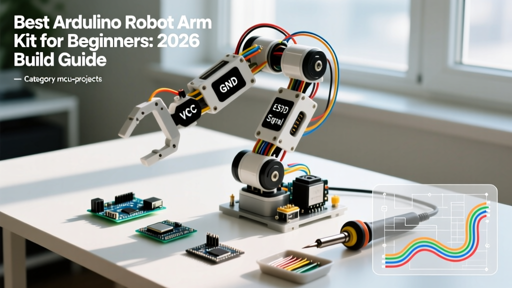
Building your first arduino robot arm kit is widely considered the ultimate rite of passage in the DIY electronics community. It bridges the gap between blinking LEDs and actual physical computing, introducing you to kinematics, torque calculations, and pulse-width modulation (PWM). As of 2026, the market for educational robotic arms has matured significantly. Acrylic chassis have been largely replaced by anodized aluminum and 3D-printed PETG composites, and metal-gear micro servos are now standard even in entry-level bundles.
However, the fundamental challenges remain the same. Beginners frequently encounter servo jitter, microcontroller brownouts, and mechanical binding. This guide will help you select the right kit, properly engineer your power delivery system, and write robust control code.
Top Arduino Robot Arm Kits Compared (2026 Market)
When shopping for an arduino robot arm kit, you are essentially buying a bundle of servos, a chassis, and a microcontroller shield. Here is how the top three beginner kits stack up this year.
| Kit Model | Degrees of Freedom (DOF) | Servo Type | Chassis Material | Avg. Price (2026) | Best For |
|---|---|---|---|---|---|
| Elegoo Unicorn V2 | 4 DOF | SG90 (Plastic Gear) | Acrylic / ABS | $42 - $48 | Absolute beginners on a strict budget |
| Adeept 5-DOF Arm | 5 DOF | MG90S (Metal Gear) | Aluminum Alloy | $65 - $75 | Intermediate builders wanting durability |
| Keyestudio Bluetooth Arm | 4 DOF | DS130 (Metal Gear) | Aluminum / Brass | $70 - $85 | IoT enthusiasts needing wireless telemetry |
Kit Selection Advice
If you are strictly learning the basic Arduino Sweep tutorial and inverse kinematics theory, the Elegoo Unicorn is perfectly adequate. However, plastic SG90 servos strip their internal gears if the arm encounters physical resistance. For a machine that can actually pick up a 50g payload (like a wooden block or a small sensor module) without catastrophic gear failure, invest in a kit featuring MG90S metal-gear servos like the Adeept model.
Deep Dive: Servo Torque and Mechanical Limits
Understanding torque is critical when assembling your arduino robot arm kit. Torque is measured in kg-cm (kilogram-centimeters). This metric tells you how much weight the servo can hold at a distance of one centimeter from the output shaft.
- SG90 (1.8 kg-cm): Can lift roughly 180 grams at a 1cm lever arm. Because robot arm segments are often 8-12cm long, the effective lifting capacity at the end-effector (the claw) drops to less than 15 grams.
- MG90S (2.2 kg-cm): Offers slightly more torque but vastly superior durability due to brass/steel internal gears. Ideal for arms up to 15cm in reach.
- DS3218 (20 kg-cm): Found in advanced kits. Requires a 6V to 8.4V power supply and heavy-duty aluminum chassis. Overkill for beginners, but necessary for payload manipulation.
Expert Warning on Chassis Flex: If you upgrade your servos to high-torque models (like the DS3218) but keep a cheap acrylic chassis, the torque will literally snap the acrylic mounting brackets during rapid directional changes. Always match your chassis rigidity to your servo torque output.
The #1 Beginner Failure Mode: Power Brownouts
Ask any robotics engineer why a beginner's robot arm twitches violently and resets the Arduino, and they will give you one answer: insufficient current delivery.
The Math Behind the Brownout
A standard Arduino Uno R3 powered via USB is limited to 500mA by the host computer's USB port. The onboard 5V voltage regulator can safely dissipate enough heat to provide maybe 800mA to the 5V pin. Now, look at your servos.
A single SG90 servo draws about 10mA at idle, but during a stall or heavy load, it can spike to 250mA. If your 4-DOF arm moves all four joints simultaneously under load, you are pulling 1000mA (1 Amp). The Arduino's voltage drops below 4.5V, the ATmega328P microcontroller experiences a brownout, the system resets, and the servos lose their PWM signal, causing the arm to go limp and crash onto your desk.
The Solution: Dedicated BEC Power
Never power more than one micro servo directly from the Arduino's 5V pin. Instead, use a dedicated BEC (Battery Eliminator Circuit) or a 5V 3A desktop power supply.
- Connect the positive (red) wire of your BEC to a breadboard's positive power rail.
- Connect the ground (black/brown) wire of your BEC to the breadboard's ground rail.
- CRITICAL STEP: Run a jumper wire from the breadboard's ground rail to one of the Arduino's GND pins. The Arduino and the servos must share a common ground reference for the PWM signals to be read correctly.
- Connect the servo power wires to the breadboard rails, and the servo signal wires directly to the Arduino's PWM pins.
For a comprehensive look at wiring safety, refer to the SparkFun Servo Hookup Guide, which details exact current draws and wire gauge recommendations.
Step-by-Step Wiring Pinout Strategy
When wiring your arduino robot arm kit, organization prevents debugging nightmares. The Arduino Uno has specific pins capable of hardware PWM (marked with a ~). While the Arduino Servo Library can generate software PWM on any digital pin, using hardware PWM pins ensures smoother, jitter-free motion.
Recommended Pin Mapping for 4-DOF Arms
- Base Rotation (Pan): Pin 9 (Handles the heaviest inertial load, benefits from stable hardware PWM).
- Shoulder Joint (Pitch): Pin 10.
- Elbow Joint (Pitch): Pin 11.
- End-Effector (Claw): Pin 6.
- I2C Sensors (if added): Leave Pins A4 and A5 open for an MPU6050 gyroscope to implement closed-loop feedback later.
Programming: Direct Recording vs. Inverse Kinematics
Once your hardware is assembled and powered correctly, you must decide how to control the arm. There are two primary paradigms for beginners.
1. Direct Joint Recording (Playback)
This is the simplest method. You use four potentiometers connected to the Arduino's analog pins (A0-A3). The Arduino reads the voltage (0-1023), maps it to a servo angle (0-180), and writes it to the servos. When you press a button, the current angles are saved to the EEPROM. Pressing another button plays the sequence back. This requires zero complex math but limits the arm to repeating exact joint movements, meaning the end-effector will move in arcs rather than straight lines.
2. Inverse Kinematics (IK)
Inverse Kinematics involves calculating the exact angles required for each joint to place the claw at a specific X, Y, Z coordinate in 3D space. While the trigonometry (involving the Law of Cosines) is daunting for absolute beginners, many 2026 kits include pre-written IK libraries. Utilizing an IK library allows you to command the arm to "move to X:10, Y:5, Z:15", and the microcontroller handles the joint interpolation. This is essential if you plan to integrate a camera for computer vision pick-and-place tasks later.
Troubleshooting FAQ
Why is my servo jittering continuously even when the code tells it to hold still?
Jitter is almost always caused by a noisy power supply or a missing common ground. If you are using a cheap switching power supply, electrical noise on the 5V rail can interfere with the PWM signal. Add a 100µF electrolytic capacitor across the power and ground rails of your servo breadboard to smooth out voltage transients.
My arm drifts slowly to one side over time. Is the servo broken?
Standard hobby servos use cheap carbon-track potentiometers for internal position feedback. Over time, and under thermal load, these potentiometers experience resistance drift. This is normal for sub-$5 servos. If precision holding is required, you must upgrade to digital servos with magnetic encoders, or implement external absolute encoders on the joints.
Can I use an ESP32 instead of an Arduino Uno for this kit?
Yes, and it is highly recommended for 2026 builds. The ESP32 offers hardware PWM channels that are vastly superior to the Arduino Uno's software-driven servo library. Furthermore, the ESP32's built-in Wi-Fi allows you to control the robot arm via a web interface or MQTT, turning your desktop kit into a fully networked IoT robotics platform.