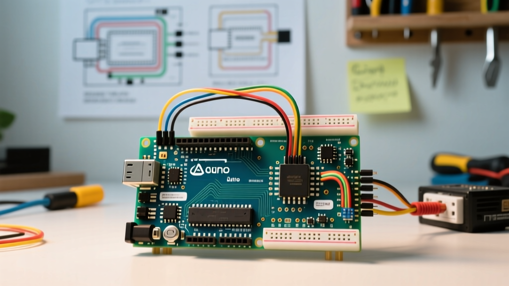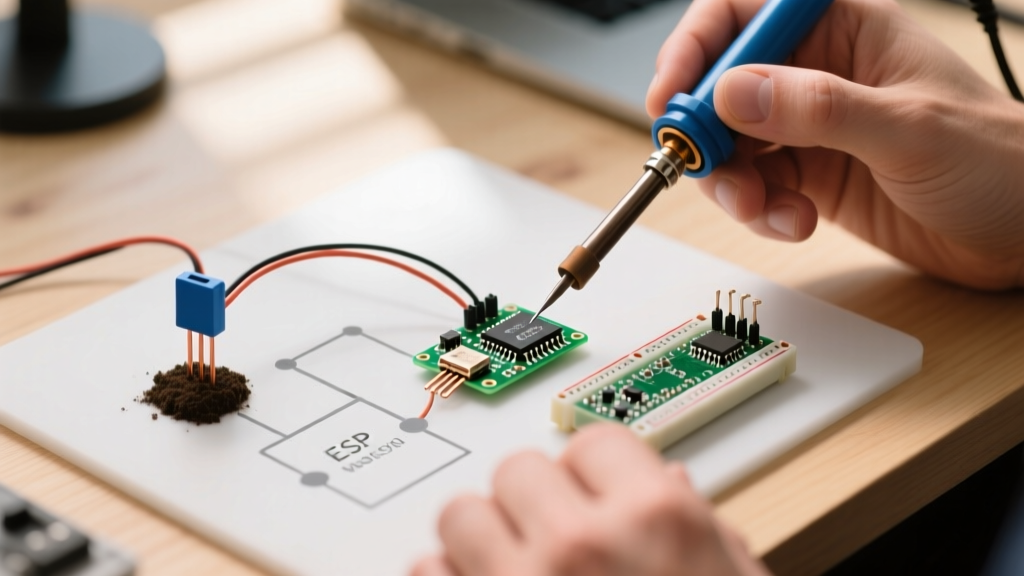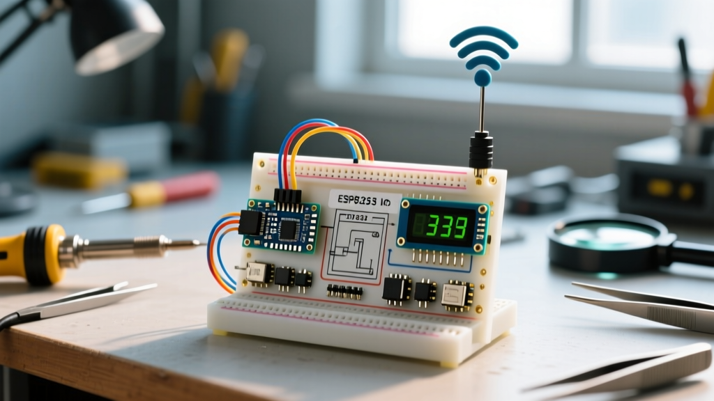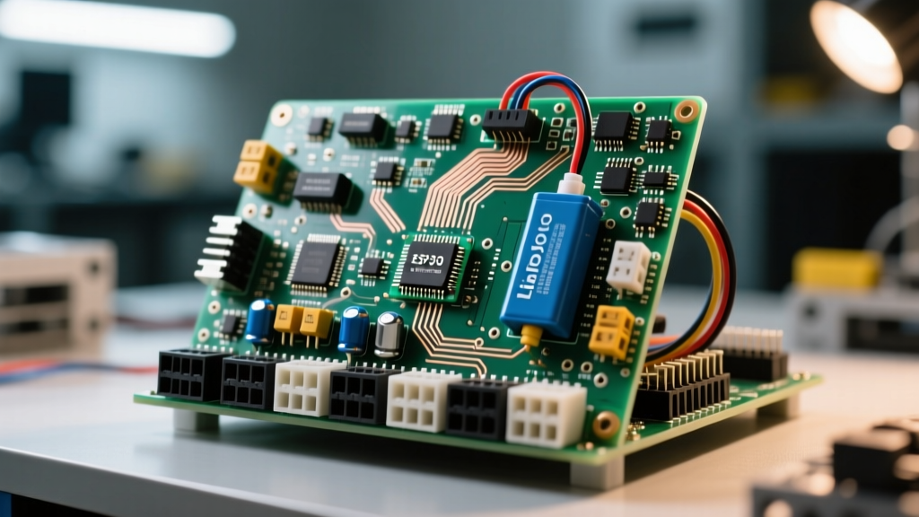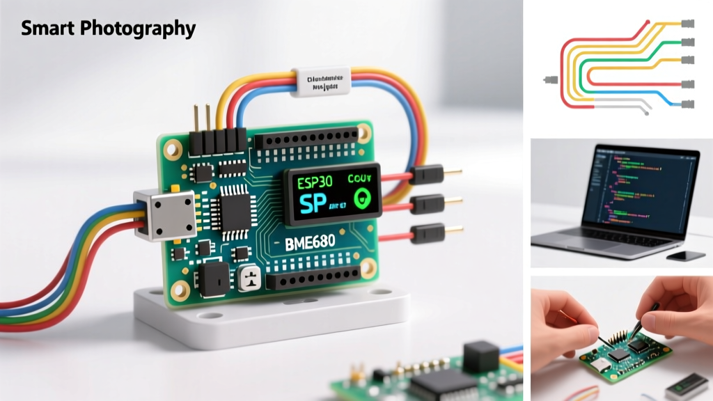

Why This Ranks Among the Arduino Best Projects
When Makers and engineers search for the arduino best projects, they are often flooded with basic LED blinkers or rudimentary weather stations. However, the true sweet spot for practical, high-impact DIY engineering lies in environmental automation. This tutorial walks you through building a Smart Climate & VOC (Volatile Organic Compounds) Hub using the ESP32-S3 and the Bosch BME680 sensor.
This build consistently ranks among the arduino best projects because it solves a critical real-world problem: monitoring and automating indoor air quality. By actively tracking VOCs and triggering HVAC boost fans or HEPA purifiers, this project aligns directly with EPA guidelines on mitigating indoor air pollutants. Below, we detail the exact hardware, wiring topology, and firmware logic required to build a commercial-grade environment hub on a DIY budget.
Bill of Materials (BOM) & Cost Breakdown
To ensure reliability, we are bypassing generic clone boards and using verified components. The total BOM cost remains under $30, making it highly accessible.
| Component | Exact Model / Specification | Est. Price | Function |
|---|---|---|---|
| Microcontroller | ESP32-S3-WROOM-1 DevKitC-1 (N8R8) | $7.50 | Dual-core 240MHz MCU with Wi-Fi/BLE |
| Environmental Sensor | Bosch BME680 Breakout (I2C) | $11.00 | Temp, Humidity, Pressure, Gas (VOC) |
| Actuator Module | 4-Channel 5V Relay with Optocouplers | $4.50 | Switches 120V/240V AC HVAC loads |
| Power Supply | 5V 3A USB-C Buck Converter Module | $3.00 | Provides clean, high-current DC power |
| Protection & Bias | 2N2222 NPN Transistors, 1N4007 Diodes, 4.7kΩ Resistors | $2.00 | Logic level shifting and flyback protection |
System Architecture & Pinout Mapping
The ESP32-S3 operates at 3.3V logic, while standard relay modules require 5V triggers. Directly connecting ESP32 GPIOs to 5V relay optocouplers often results in failure to trigger or back-feeding voltage that damages the MCU. We use a transistor-based low-side switching topology.
- BME680 SDA: GPIO8 (Requires 4.7kΩ pull-up to 3.3V)
- BME680 SCL: GPIO9 (Requires 4.7kΩ pull-up to 3.3V)
- Relay 1 (Fan): GPIO38 (Via 2N2222 Base Resistor)
- Relay 2 (Purifier): GPIO39 (Via 2N2222 Base Resistor)
- Relay 3 (Damper): GPIO40 (Via 2N2222 Base Resistor)
- Relay 4 (Alarm): GPIO41 (Via 2N2222 Base Resistor)
Step 1: I2C Sensor Integration & Pull-Up Requirements
The BME680 communicates via I2C. While the Arduino Wire Library Reference enables internal pull-ups on the MCU, these internal resistors (typically 45kΩ) are far too weak for reliable high-speed I2C communication, especially if your sensor is mounted more than 10cm away from the ESP32 via ribbon cable.
Actionable Build Step: Solder 4.7kΩ through-hole resistors directly between the SDA/VCC and SCL/VCC lines on your custom perfboard or PCB. This guarantees sharp signal edges and prevents I2C bus lockups caused by capacitive loading on the wires. Ensure the BME680's I2C address jumper is set to 0x76 (default) or 0x77 if you need to share the bus with another sensor.
Step 2: Relay Driving & Flyback Protection
Electromechanical relays contain inductive coils. When the transistor cuts power to the coil, the collapsing magnetic field generates a massive reverse voltage spike (inductive kickback) that can easily exceed 50V, instantly destroying your ESP32-S3's GPIO pins.
Actionable Build Step: You must solder a 1N4007 flyback diode in reverse bias (cathode stripe facing the 5V VCC, anode facing the transistor collector) across every single relay coil. Furthermore, place a 1kΩ current-limiting resistor between the ESP32 GPIO and the base of the 2N2222 NPN transistor. This limits base current to roughly 2.6mA, well within the ESP32's 40mA absolute maximum GPIO rating, while providing enough gain to saturate the transistor and switch the 80mA relay coil.
Step 3: Firmware Logic & The BME680 Burn-In Phase
A common reason Makers abandon environmental projects is inaccurate gas sensor readings right out of the box. According to the Bosch Sensortec BME680 Documentation, the metal-oxide (MOX) gas sensor requires a continuous thermal burn-in period to stabilize the heater element and outgas manufacturing residues.
Expert Tip: Do not calibrate your VOC thresholds on day one. Write your firmware to log data to an SD card or local MQTT broker continuously for the first 48 to 72 hours. Only after this burn-in period should you establish your baseline 'clean air' resistance value (typically between 50kΩ and 150kΩ in a standard indoor environment).
In your Arduino IDE code, utilize the bme.performReading() function, but implement a non-blocking millis() timer to poll the sensor only once every 10 seconds. Polling the MOX heater too frequently alters its thermal profile and skews the temperature and humidity readings located on the same silicon die.
Power Budget Analysis
Many DIY builds fail due to brownouts when Wi-Fi transmits and relays switch simultaneously. Let us calculate the exact peak power budget:
- ESP32-S3 Baseline: ~80mA
- ESP32-S3 Wi-Fi TX Peak: ~240mA
- BME680 Sensor: ~1.2mA
- 4-Channel Relays (All ON): 4 x 80mA = 320mA
- Total Peak Draw: ~561.2mA
By utilizing a 5V 3A (3000mA) USB-C buck converter, we maintain an 80% safety margin. Never power this specific build directly from a standard 500mA PC USB port; the voltage drop during Wi-Fi beacon transmissions will trigger the ESP32's internal brownout detector (BOD), causing endless reboot loops.
Troubleshooting Edge Cases
1. Wi-Fi Antenna Detuning & EMI
If your ESP32-S3 constantly drops its Wi-Fi connection when the relays click, you are experiencing Electromagnetic Interference (EMI). The 2.4GHz Wi-Fi antenna on the DevKitC-1 is highly sensitive to nearby metal and high-current switching. Fix: Keep all relay wiring and AC mains traces at least 5cm away from the ESP32 antenna overhang. If using a metal enclosure, you must use an external RP-SMA antenna with a pigtail to route the RF outside the chassis.
2. BME680 Humidity Sticking at 99%
If the sensor reports 99% humidity and refuses to drop, the sensor's humidity membrane has likely become saturated or contaminated by flux residue from sloppy soldering. Fix: Never use acid-core solder, and avoid cleaning the BME680 breakout with harsh isopropyl alcohol baths that can wick under the sensor lid. If contaminated, bake the sensor board at 60°C in a dry environment for 4 hours to evaporate trapped moisture.
Conclusion
Building a Smart Climate Hub elevates your portfolio from simple prototypes to robust, life-improving automation. By addressing hardware protection (flyback diodes), signal integrity (I2C pull-ups), and sensor physics (MOX burn-in), you ensure your project operates flawlessly for years. This level of engineering rigor is exactly what separates fleeting weekend experiments from the true arduino best projects that earn a permanent place in your smart home ecosystem.