
The Evolution of Arduino Projects with Servos
When most makers search for arduino projects with servos, they inevitably stumble upon the same beginner tutorials: a basic sweeping arm, a simple radar plotter, or a two-wheel obstacle-avoiding car. While these are excellent for learning PWM (Pulse Width Modulation) signals, they rarely survive contact with real-world physical forces. True home and agricultural automation requires moving heavy loads based on dynamic environmental data.
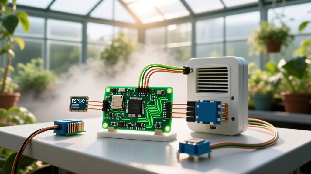
In 2026, the accessibility of high-torque metal-gear servos and precision I2C environmental sensors has completely transformed what is possible on a workbench. In this guide, we are abandoning the micro-servos and building a Sensor-Driven Greenhouse Vent & Shading Controller. This project fuses temperature, humidity, and lux data to actuate heavy acrylic roof vents, requiring deep knowledge of torque physics, power isolation, and control hysteresis.
Component Selection and the Torque Trap
The most common point of failure in advanced servo projects is underestimating mechanical load. A standard greenhouse vent window weighs roughly 2.5 kg. If your servo arm (lever) is 15 cm long, the physics dictate a massive torque requirement.
Calculating the Required Torque
- Force (F): 2.5 kg × 9.81 m/s² = 24.5 Newtons.
- Torque (τ): 24.5 N × 0.15 m (lever arm) = 3.67 Nm.
- Conversion: 3.67 Nm is approximately 37.4 kg/cm.
Most hobbyists grab an MG996R (13 kg/cm) and wonder why the servo strips its internal gears or overheats on day one. You need a servo rated for at least 45 kg/cm to account for friction, wind load, and mechanical binding.
| Servo Model | Torque @ 6V | Stall Current | Best Use Case | Approx. Price (2026) |
|---|---|---|---|---|
| SG90 (Micro) | 1.8 kg/cm | 650 mA | Indicators, lightweight flaps | $2.50 |
| MG996R (Metal Gear) | 13 kg/cm | 2.5 A | Robot chassis, pan/tilt cameras | $7.00 |
| DS3218 (270°) | 20 kg/cm | 3.0 A | Robotic arms, winches | $16.00 |
| DS51150 (Heavy Duty) | 45 kg/cm | 4.5 A | Greenhouse vents, heavy latches | $32.00 |
Power Architecture: Preventing the Brownout Crash
When the DS51150 servo hits a mechanical bind or reaches its stall torque, it will pull up to 4.5 Amps instantaneously. If you are powering your Arduino and servo from the same 5V USB rail, this current spike will cause a massive voltage droop. The Arduino’s ATmega328P or ESP32 will brownout, reset, and send erratic PWM signals, causing the servo to violently thrash and destroy your physical linkage.
The Isolated Power Topology
To build reliable sensor-driven Arduino projects with servos, you must separate the logic power from the actuator power.
- Logic Supply: Power the Arduino via its onboard regulator or a dedicated 5V 1A buck converter.
- Actuator Supply: Use a Mean Well IRM-30-5ST (5V 6A AC-DC module) or an LM2596 buck converter fed by a 12V 10A battery/solar setup.
- The Golden Rule of Grounding: The Ground (GND) of the servo power supply must be tied directly to the Arduino GND. Without a common ground reference, the Arduino's PWM signal will float, resulting in severe servo jitter. However, tie them at the power supply terminals, not through the Arduino's thin header pins, to keep high-current ground bounce away from the microcontroller's logic ground.
- Capacitive Buffering: Solder a 1000µF electrolytic capacitor and a 0.1µF ceramic capacitor in parallel across the 5V and GND rails directly at the servo terminals to absorb transient spikes.
Sensor Fusion: Reading the Environment
A smart vent shouldn't just open when it's hot; it must consider humidity and light to prevent crop stress. We use two I2C sensors for this:
- BME280: Measures temperature, humidity, and barometric pressure. Unlike the older DHT11, the BME280 offers I2C communication, fast polling, and high accuracy (±1°C, ±3% RH). Refer to the Adafruit BME280 Guide for exact wiring and I2C pull-up resistor requirements.
- BH1750: A digital ambient light sensor that outputs Lux directly, bypassing the need for analog-to-digital conversion and voltage divider math required by basic LDRs.
Wiring Note: Both sensors share the I2C bus (SDA/SCL). The BME280 default address is usually 0x76 or 0x77, while the BH1750 sits at 0x23. Ensure your I2C lines have 4.7kΩ pull-up resistors to 3.3V if your Arduino board doesn't include them natively.
Control Logic: Implementing Hysteresis
Beginner code often looks like this: if (temp > 25) openVent(); else closeVent();. In the real world, temperature fluctuates by fractions of a degree due to wind or passing clouds. This naive logic causes the servo to rapidly open and close ("hunting"), burning out the internal potentiometer and drawing continuous stall current.
The Deadband Solution
We implement a software hysteresis loop (a deadband). The vent opens at 27°C, but does not begin closing until the temperature drops to 24°C. Furthermore, we map the servo position proportionally rather than using simple bang-bang control.
Pro-Tip for PWM Jitter: The standard Arduino Servo Library uses Timer1, which can sometimes conflict with I2C or specific PWM pins. If your servo twitches when the BME280 is polled, detach the servo after it reaches its target position using
myServo.detach(). This stops the continuous PWM signal, eliminating holding jitter and saving power, provided your mechanical linkage is self-locking or gravity-assisted.
Real-World Failure Modes and Troubleshooting
Even with perfect code, physical environments are harsh. Here are the edge cases you must design for:
1. Potentiometer Dead-Zone Wear
Standard servos use a physical carbon-track potentiometer for position feedback. If your vent rests at exactly 90° for months, the physical wiper wears a dead spot into the carbon track. When the servo finally tries to move, it reads erratic resistance values and oscillates violently. Solution: Program a "maintenance sweep" in your code that moves the servo ±2° every 24 hours to distribute wear, or upgrade to a magnetic encoder servo (e.g., LewanSoul bus servos) which have no physical contact wear.
2. Mechanical Binding and Stall Currents
Wooden greenhouse frames warp with humidity. A vent that moves freely in winter may bind in the summer. If the servo stalls, it will pull 4.5A continuously, melting standard 22AWG jumper wires. Solution: Use 16AWG silicone wire for the servo power leads, and implement a current sensor (like the INA219) in series with the servo ground. If the code detects current > 2A for more than 500ms, it must immediately cut power via a logic-level MOSFET (e.g., IRLZ44N) and trigger an alert.
3. Lightning and Ground Loops
Running long I2C sensor cables outside to a greenhouse invites induced voltage spikes from nearby lightning or heavy machinery. Solution: Do not run raw I2C over cables longer than 30cm. Instead, place a secondary microcontroller (like an ATtiny85 or ESP8266) inside the sensor housing outside, and transmit the data back to the main Arduino via an isolated RS485 bus or optical isolators.
Conclusion
Building advanced arduino projects with servos requires stepping away from the breadboard and thinking like a mechanical and power engineer. By calculating true torque requirements, isolating your power domains, and writing defensive code with hysteresis and stall-protection, you transform a simple hobby motor into a reliable, heavy-duty agricultural actuator. For more foundational servo sweeping mechanics, review the classic Arduino Sweep Tutorial, then scale up your designs to handle the real world.