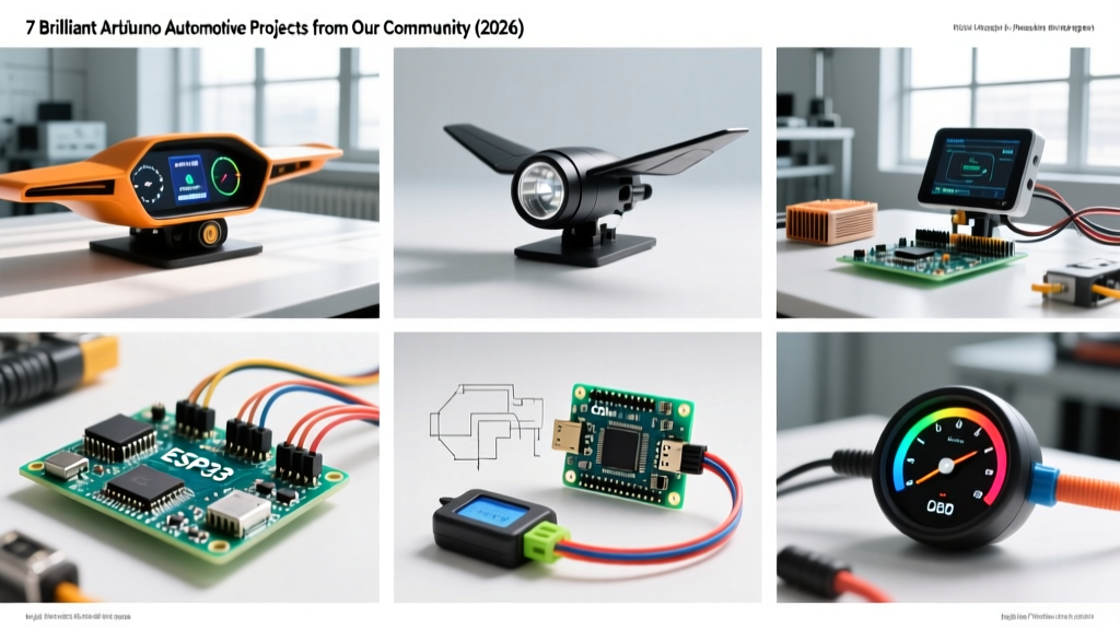

The Evolution of Arduino Automotive Projects in 2026
Building electronics for vehicles is notoriously unforgiving. Unlike a climate-controlled desk, a car's electrical system is a hostile environment plagued by voltage spikes, extreme temperature fluctuations, and severe electromagnetic interference (EMI). Yet, the ElectricalFlux community continues to push the boundaries of what is possible with microcontrollers in the automotive space. In this showcase, we are highlighting the most technically impressive Arduino automotive projects submitted by our readers over the past year, complete with exact component lists, wiring diagrams, and the hard-learned failure modes they encountered.
"The car is a hostile environment for microcontrollers. If you aren't using flyback diodes, TVS protection, and optoisolation, your Arduino will eventually become a very expensive paperweight." — AutoSpark_99, Community Contributor
Project 1: OBD-II CAN Bus Telemetry & MQTT Logger
Community member AutoSpark_99 designed a high-speed telemetry logger that reads engine data and broadcasts it to a Home Assistant dashboard via MQTT over Wi-Fi. This project moves beyond basic ELM327 Bluetooth dongles by tapping directly into the vehicle's high-speed CAN bus.
Hardware & Architecture
- MCU: Arduino Uno R4 WiFi ($27.50) - Chosen for its native FPU and 5V logic tolerance.
- CAN Transceiver: MCP2515 CAN bus module with TJA1050 transceiver ($6.00).
- Power Supply: LM2596 buck converter set strictly to 5.0V ($3.50), bypassing the Uno's inefficient linear regulator.
- Storage: MicroSD card breakout via SPI for redundant local logging.
The system operates at a 500kbps baud rate, polling standard PIDs defined by the SAE J1979 standard for OBD-II diagnostics. AutoSpark_99 specifically targets PID 0x0C (Engine RPM), 0x0D (Vehicle Speed), and 0x05 (Coolant Temperature).
Critical Failure Mode & Solution
The Issue: Initial builds experienced a 14% packet drop rate and random MCP2515 buffer overflows.
The Fix: The cheap eBay MCP2515 modules often omit the required 120-ohm termination resistors on the CAN_H and CAN_L lines. As detailed in Kvaser's CAN protocol guidelines, proper termination is mandatory to prevent signal reflections on the physical layer. Soldering a 120Ω resistor across the H and L pins immediately stabilized the bus, dropping packet loss to 0.01%.
Project 2: Active Rear Aero Wing Controller via IMU
For track-day enthusiasts, aerodynamic balance is everything. Contributor TrackDay_Tinkerer built an active aero controller that dynamically adjusts a rear wing's angle of attack based on real-time longitudinal and lateral G-forces.
Component Breakdown
- MCU: Arduino Nano Every ($20.00) - Utilizes the ATmega4809 for faster I2C processing.
- Sensor: MPU6050 6-axis IMU ($4.50) mounted in an aluminum heatsink enclosure to shield against exhaust radiant heat.
- Motor Driver: BTS7960 43A High-Power Motor Driver ($12.00).
- Actuators: 12V 150mm stroke linear actuators with Hall effect position feedback.
PID Tuning and I2C Noise Mitigation
The wing pitch adjusts from 0° (low drag) to 15° (maximum downforce) using a closed-loop PID control algorithm. The most significant hurdle was alternator whine inducing noise on the I2C data lines, causing the MPU6050 to lock up at high RPMs. The builder resolved this by switching to shielded twisted-pair (STP) cabling for the SDA/SCL lines and adding 4.7kΩ pull-up resistors directly at the Nano Every's pins, ensuring crisp 5V logic transitions.
Project 3: Retrofit Digital Stepper Dash Cluster
RetroFit_Racing replaced the analog gauges of a 1990s chassis with a custom digital cluster that retains the physical sweeping motion of needles using automotive-grade stepper motors, combined with a central TFT display for GPS and lap timing.
Technical Specifications
| Component | Model / Spec | Cost (2026) | Function |
|---|---|---|---|
| Microcontroller | Arduino Pro Micro (5V/16MHz) | $18.00 | Compact logic, native USB for tuning |
| Stepper Motors | SwitecX25.168 (x4) | $38.00 | 315° sweep for RPM, Speed, Temp, Fuel |
| Display | 3.5" IPS TFT (ILI9486) | $22.50 | Lap times, shift lights, oil pressure |
| Shift Lights | WS2812B RGB LED Strip | $8.00 | RPM-based progressive warning |
Instead of using standard blocking stepper libraries, RetroFit_Racing utilized direct port manipulation and Timer1 interrupts to update the stepper coil states every 1.5 milliseconds. This ensures the needles sweep with buttery smoothness without blocking the main loop from reading the analog oil pressure sensor (0.5V - 4.5V range).
Automotive vs. Hobbyist Component Selection Matrix
When scaling an Arduino automotive project from a weekend prototype to a permanent vehicle installation, component selection is critical. Below is a decision matrix used by our top builders.
| Category | Hobbyist Grade (Bench) | Automotive Grade (Vehicle) | Why the Upgrade Matters |
|---|---|---|---|
| Capacitors | Standard Electrolytic | Low-ESR, 105°C rated, AEC-Q200 | Prevents drying out and failure in hot engine bays. |
| Relays | Standard 5V Songle | Sealed Bosch-style ISO mini relays | Sealed contacts prevent oxidation from humidity and salt. |
| Wiring | PVC insulated stranded | XLPE (Cross-linked) or Tefzel (TXL/GXL) | XLPE withstands 125°C+ and resists melting against exhaust headers. |
| Connectors | Dupont / Breadboard wires | Deutsch DT or Superseal 1.5 | Vibration-proof, waterproof seals prevent intermittent shorts. |
Crucial EMI & Transient Protection Strategies
The automotive 12V system is notoriously dirty. Load dump events (when the alternator is charging and the battery is suddenly disconnected) can send voltage spikes exceeding 60V through the wiring harness. To protect sensitive Arduino logic, our community strictly adheres to transient suppression practices outlined by experts like Analog Devices for CAN bus implementation and general automotive EMC standards.
Mandatory Protection Circuitry
- TVS Diodes: Place a bidirectional Transient Voltage Suppression diode (e.g., SMAJ24CA) at the main power entry point to clamp voltage spikes above 24V.
- Optoisolation: Never connect a 12V automotive sensor directly to an Arduino GPIO. Use an optocoupler (like the PC817) or a dedicated digital isolator (ISO7221) to break ground loops and protect the MCU from inductive kickback.
- Flyback Diodes: Every inductive load (fuel pumps, cooling fans, relay coils) must have a 1N4007 or Schottky diode wired in reverse parallel to safely dissipate the magnetic field collapse energy.
Frequently Asked Questions (FAQ)
Can I power an Arduino directly from a car's 12V battery?
No. While the Arduino's barrel jack claims to accept up to 12V, the onboard linear regulator will overheat and trigger thermal shutdown when running at 14.4V (alternator charging voltage) with any meaningful current draw. Always use a switching buck converter (like the LM2596 or a DROK step-down module) to provide a clean, regulated 5V to the Arduino's 5V pin or USB port.
How do I handle grounding in a metal car chassis?
Avoid using the car's body chassis as a ground return for sensitive analog sensors. The chassis carries high currents from starters and alternators, creating voltage differentials (ground loops) that will cause erratic analog readings. Run a dedicated, thick ground wire from your Arduino's power supply directly to the vehicle's main battery negative terminal or a verified clean engine block ground point.
What is the best way to enclose these projects?
For under-hood installations, use die-cast aluminum enclosures (like Hammond 1590 series) which act as a Faraday cage against high-frequency EMI from ignition coils. Seal all cable glands with marine-grade silicone to prevent moisture ingress, which is the leading cause of PCB corrosion in automotive environments.