
Why Your Arduino Needs a Dedicated Stepper Driver
If you are building a CNC plotter, a 3D printer, or a precision robotics arm, you will inevitably need to control a stepper motor. However, you cannot connect a stepper motor directly to an Arduino Uno R3 or R4. The ATmega328P and Renesas RA4M1 microcontrollers on these boards can only safely source about 20mA to 40mA per I/O pin. A standard NEMA 17 stepper motor (like the popular 17HS4401) requires roughly 1.5 Amps per phase to generate its rated 42 N⋅cm of holding torque.
Attempting to drive a motor directly will instantly fry your microcontroller. This is why selecting and wiring the correct stepper motor driver for Arduino is the most critical step in your peripheral interfacing journey. The driver acts as a high-current buffer, translating low-voltage logic pulses from your Arduino into high-current, sequenced power outputs that drive the motor coils.
Choosing the Right Stepper Motor Driver for Arduino
Not all drivers are created equal. In 2026, the market is dominated by three main carrier boards for hobbyists and entry-level industrial prototyping. Here is how they stack up against each other:
| Driver IC | Max Current (No Cooling) | Max Microstepping | Noise Level | Avg. Price (2026) | Best Use Case |
|---|---|---|---|---|---|
| A4988 | 1.0A | 1/16 | Loud (Whine) | $1.50 - $2.50 | Basic pan/tilt cameras, simple conveyors |
| DRV8825 | 1.5A | 1/32 | Moderate | $2.00 - $3.50 | Desktop CNCs, 3D printer extruders |
| TMC2209 | 1.7A (2.0A peak) | 1/256 (via UART) | Silent (StealthChop) | $6.00 - $9.00 | High-end 3D printers, quiet robotics |
For this tutorial, we will focus on the DRV8825. It offers the best balance of price, torque handling, and microstepping resolution for beginners stepping up from the A4988. You can verify the exact pinout and thermal characteristics on the Pololu DRV8825 Stepper Motor Driver Carrier documentation page.
Essential Hardware Bill of Materials
- Microcontroller: Arduino Uno R3 or R4 Minima
- Driver: DRV8825 Carrier Board (HiLetgo or Pololu brand recommended)
- Motor: NEMA 17 Stepper Motor (e.g., 17HS4401, 1.5A/phase, 200 steps/rev)
- Power Supply: 12V 5A DC Switching Power Supply (Mean Well LRS-60-12 or equivalent, ~$14)
- Capacitor: 100µF 35V Electrolytic Capacitor (Crucial for spike suppression)
- Tools: Digital Multimeter, small ceramic flathead screwdriver (metal shafts can cause short circuits during tuning)
Step-by-Step Wiring Guide
Wiring a stepper motor driver for Arduino requires separating your high-power motor circuit from your low-power logic circuit. Follow these connections exactly:
1. Power and Protection (The VMOT Circuit)
Connect the positive terminal of your 12V power supply to the VMOT pin on the DRV8825, and the negative terminal to the GND pin.
CRITICAL WARNING: You MUST solder or plug a 100µF electrolytic capacitor directly across the VMOT and GND pins, as close to the board as possible. Stepper motors generate massive inductive voltage spikes when coils are energized and de-energized. Without this decoupling capacitor, these spikes will exceed the DRV8825's 45V absolute maximum rating and permanently destroy the internal H-bridge MOSFETs.
2. Identifying and Connecting Motor Coils
A NEMA 17 motor has two internal coils, resulting in four wires. Do not rely on wire colors, as manufacturers frequently change them. Instead, use your multimeter in continuity mode to find the pairs. Two wires that show continuity (a near-zero ohm reading) belong to the same coil. Connect one pair to 1A and 1B, and the second pair to 2A and 2B.
3. Logic and Control Pins (Arduino Side)
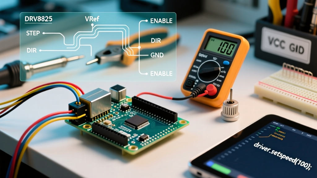
Ensure your Arduino and the 12V power supply share a common ground (connect the Arduino GND to the DRV8825 GND). Then, wire the control pins:
- STEP: Arduino Digital Pin 3 (Must be a PWM-capable or interrupt-capable pin for some libraries, though standard digital works for AccelStepper)
- DIR: Arduino Digital Pin 4
- SLP (Sleep): Connect to Arduino 5V (Must be HIGH to operate)
- RST (Reset): Connect to Arduino 5V (Must be HIGH to operate)
- EN (Enable): Connect to Arduino GND (LOW enables the driver; leave floating or HIGH to disable)
The Most Skipped Step: Setting the Current Limit (Vref)
Before you upload a single line of code, you must tune the DRV8825's current limit. Out of the box, the potentiometer on the carrier board is set to a random value. If it is set too high, your NEMA 17 motor will overheat, lose torque, and eventually demagnetize. If it is set too low, the motor will stutter and miss steps.
The Texas Instruments DRV8825 Datasheet defines the current limit formula as:
Current Limit = VREF × 2
Therefore, to find your target VREF voltage:
VREF = Current Limit / 2
If your 17HS4401 motor is rated for 1.5A, your target VREF is 0.75V.
How to Measure and Tune VREF:
- Power on the Arduino (via USB) and the 12V motor power supply. Do not disconnect the motor while the driver is powered.
- Set your digital multimeter to DC Voltage (2000mV or 2V range).
- Place the black probe on any ground connection (the metal barrel of the Arduino USB port works perfectly).
- Place the red probe gently on the metal pad of the trimmer potentiometer on the DRV8825 (or the TP1 test point if your specific board has one).
- Using your ceramic screwdriver, turn the potentiometer. Clockwise increases the voltage; counter-clockwise decreases it.
- Adjust until your multimeter reads exactly 0.75V.
The Microstepping Reality Check
The DRV8825 supports up to 1/32 microstepping. By setting the M0, M1, and M2 pins to specific HIGH/LOW combinations, you can divide a full step into 32 microsteps. However, beginners often confuse microstepping with accuracy.
Microstepping is primarily a resonance damping and smoothing technique, not a precision multiplier. A standard NEMA 17 motor has a mechanical manufacturing tolerance of ±5% per full step (which is ±0.9° on a 200-step motor). When you command a 1/32 microstep, the rotor does not reliably move exactly 0.056°. The magnetic detent torque and friction will cause the rotor to 'snap' to the nearest full-step equilibrium point under load. Use 1/16 or 1/32 microstepping to eliminate the high-pitched whining noise and low-speed vibration, but rely on mechanical gearing or lead screws if you need true sub-millimeter positional accuracy.
Writing the Arduino Code with AccelStepper
Do not use the default Stepper.h library included in the Arduino IDE. It sends pulses at a constant, abrupt rate, which will cause your motor to stall immediately upon startup due to rotor inertia. Instead, install the AccelStepper Library by Mike McCauley via the Arduino Library Manager. This library calculates smooth acceleration and deceleration ramps.
#include <AccelStepper.h>

// Define the stepper and the pins it uses
// AccelStepper::DRIVER means we are using a dedicated STEP/DIR driver board
AccelStepper stepper(AccelStepper::DRIVER, 3, 4); // Pin 3 = STEP, Pin 4 = DIR

void setup() {
  // Set the maximum permitted speed.
  // For 1/16 microstepping, 800 steps = 1 revolution.
  stepper.setMaxSpeed(1600); // 2 revolutions per second max

  // Set the acceleration.
  // Start low to prevent stalling, increase once tuned.
  stepper.setAcceleration(400);

  // Move to a target position (e.g., 5 full revolutions at 1/16 stepping = 8000 steps)
  stepper.moveTo(8000);
}

void loop() {
  // If at the end of travel, reverse direction
  if (stepper.distanceToGo() == 0) {
    stepper.moveTo(-stepper.currentPosition());
  }

  // Must be called as frequently as possible to step the motor
  stepper.run();
}
Real-World Troubleshooting & Edge Cases
Even with perfect wiring, electromechanical systems present unique failure modes. Here is how to diagnose the most common issues when integrating a stepper motor driver for Arduino:
1. The Motor Vibrates but Does Not Spin
Cause: The pulse rate is too high for the motor's inertia, or the acceleration is set too aggressively in the code. Alternatively, the current limit (Vref) is too low, providing insufficient torque to break the rotor's magnetic detent.
Fix: Lower the setMaxSpeed() and setAcceleration() values in your code by 50%. If the issue persists, increase your VREF by 0.1V increments.
2. The DRV8825 Chip is Too Hot to Touch
Cause: The DRV8825 can handle 1.5A without a heatsink, but only with adequate airflow. In a stagnant enclosure, the thermal shutdown will trigger at around 150°C junction temperature.
Fix: Stick a small aluminum heatsink (usually included with the carrier board) onto the IC. If it is still overheating, you are likely commanding too much holding current while the motor is stationary. Use the EN (Enable) pin to completely cut power to the coils when the motor does not need to hold position.
3. Erratic Direction Changes or Missed Steps
Cause: Electromagnetic interference (EMI) from the stepper coils is inducing noise on the STEP and DIR logic lines, especially if you are using long, unshielded ribbon cables between the Arduino and the driver.
Fix: Keep logic wires under 30cm in length. If you must use long runs, use twisted-pair cables for the STEP/DIR signals or opt for differential line drivers (like the RS-422 standard) commonly found in professional CNC controller boards.
Mastering the interfacing of a stepper motor driver for Arduino bridges the gap between simple LED-blinking projects and real-world kinetic engineering. By respecting the electrical limits, properly tuning the VREF, and utilizing ramping libraries, you ensure your electromechanical builds operate smoothly and reliably for years to come.