
Beyond the Breadboard: Engineering a Robust Arduino Screen LCD Deployment
Integrating an arduino screen lcd into a desktop prototype is a rite of passage for embedded developers. However, deploying that same 20x4 character display inside a humid greenhouse, a vibrating industrial control panel, or an outdoor weather station introduces a host of electrical and environmental failures. Tutorials rarely address I2C bus capacitance, logic-level mismatches, or the physical limitations of nematic liquid crystals.
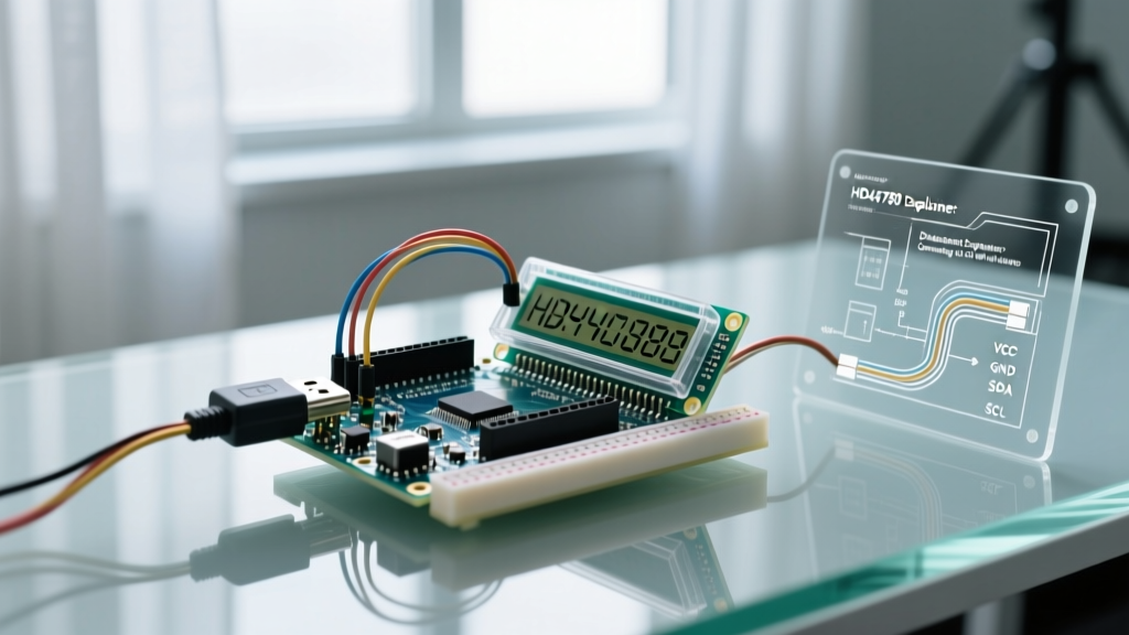
This guide bridges the gap between basic wiring diagrams and robust, real-world engineering. We will focus on the industry-standard 20x4 HD44780 display equipped with a PCF8574 I2C backpack, analyzing the specific edge cases that cause field deployments to fail and providing actionable, code-level solutions for 2026 hardware ecosystems.
Hardware BOM and 2026 Market Realities
When sourcing components for field-deployable sensor dashboards, component selection dictates long-term reliability. Below is a realistic Bill of Materials (BOM) optimized for a mixed-signal sensor node.
| Component | Specific Model / Part Number | Approx. 2026 Cost | Engineering Notes |
|---|---|---|---|
| Display Module | 20x4 HD44780 with PCF8574 I2C Backpack | $8.50 - $12.00 | Ensure the backpack uses the PCF8574T (0x27) or PCF8574AT (0x3F) to avoid address conflicts. |
| Microcontroller | Arduino Nano 33 IoT (ABX00027) | $22.00 | Native 3.3V logic and WiFi/BLE. Requires level shifting for the 5V LCD. |
| Logic Level Shifter | BSS138 Bidirectional I2C Shifter (Adafruit 757) | $3.95 | Mandatory when interfacing 3.3V MCUs with 5V I2C pull-ups. |
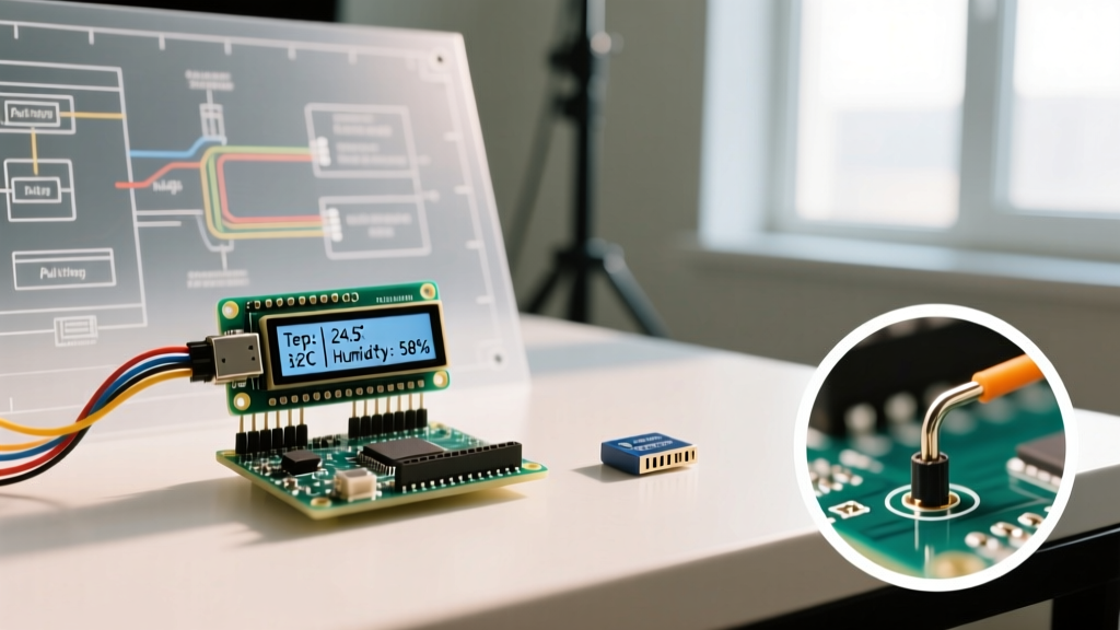
| Environmental Sensor | Sensirion SHT40 (I2C) | $6.50 | High-accuracy temp/humidity. Shares the I2C bus with the LCD. |
The Physics of I2C: Overcoming Bus Capacitance
The most common reason an arduino screen lcd fails in a real-world enclosure is not a software bug, but I2C signal degradation. The I2C specification dictates a maximum bus capacitance of 400pF. When you mount your LCD inside a polycarbonate enclosure and route cables from your microcontroller, you introduce parasitic capacitance.
- Wire Capacitance: Standard CAT5e twisted pair cable adds approximately 50pF per meter.
- Node Capacitance: The PCF8574 backpack, the Arduino pins, and the SHT40 sensor each add 10pF to 20pF.
If you run 4 meters of cable to your display, you add 200pF. Combined with the nodes, you approach the 400pF limit. The result? The SDA and SCL rise times become too slow, the Arduino misses the ACKnowledge (ACK) bit, and the LCD freezes or displays garbage characters.
Engineering Solutions for Long Cable Runs
Pro-Tip: If your I2C bus exceeds 2 meters, drop the clock speed. By default, the Arduino Wire library operates at 100kHz, but many modern boards push 400kHz (Fast Mode). Forcing the bus back to standard mode provides more time for the voltage to rise across the parasitic capacitors.
Implement this in your setup() function using the Arduino Wire Library Reference:
Wire.begin();
Wire.setClock(100000); // Force 100kHz Standard Mode for high-capacitance runs
For runs exceeding 5 meters, software tweaks are insufficient. You must use an active I2C bus extender IC, such as the NXP P82B715, which buffers the I2C signals into a differential-like current loop, completely ignoring the 400pF capacitance limit.
The 3.3V vs 5V Logic Trap
In 2026, the majority of professional IoT microcontrollers (ESP32-S3, Arduino Nano 33, Raspberry Pi Pico) operate at 3.3V logic. However, the ubiquitous PCF8574 I2C backpacks are designed for 5V systems. The pull-up resistors on the backpack are tied directly to the VCC pin.
If you power the backpack with 5V to ensure the LCD contrast is stable, the SDA and SCL lines are pulled up to 5V. Feeding 5V directly into the 3.3V GPIO pins of an Arduino Nano 33 IoT will overstress the internal ESD protection diodes, leading to premature silicon degradation and erratic I2C behavior.
The BSS138 Solution
You must place a BSS138-based bidirectional logic level shifter between the microcontroller and the LCD backpack. The BSS138 MOSFET isolates the 3.3V and 5V domains while allowing the open-drain I2C signals to pass seamlessly. Do not rely on simple voltage divider resistor networks for I2C; the asymmetric pull-up/pull-down timing will corrupt the data stream.
Thermal Limitations of Nematic Liquid Crystals
When specifying an arduino screen lcd for outdoor or unheated warehouse deployments, you must account for the physics of the display fluid. The HD44780 utilizes nematic liquid crystals, which are highly temperature-dependent.
- Optimal Range: 20°C to 30°C (Response time < 5ms).
- Cold Weather (< 0°C): The fluid viscosity increases drastically. Response times stretch past 500ms, causing severe ghosting, trailing characters, and eventual freezing of the display matrix.
- High Heat (> 50°C): The fluid becomes isotropic, and the display turns completely black or washes out until it cools down.
Field Fix: If your deployment environment drops below freezing, abandon the HD44780. Switch to a 20x4 OLED module (SSD1315 controller) or a transflective TFT display, which do not rely on liquid crystal phase shifts and operate reliably down to -40°C. For cold-weather LCDs, you must integrate a polyimide heating element behind the glass, driven by a PWM-controlled MOSFET, to maintain the glass at 15°C.
Non-Blocking C++ Architecture for Sensor Dashboards
Updating an LCD via I2C is a relatively slow process. Transmitting a 20-character string at 100kHz takes roughly 2 milliseconds. If you use delay() to pace your screen updates, you block the microcontroller from polling time-critical sensors or maintaining WiFi connections.
Below is a production-ready, non-blocking architecture using millis() to decouple sensor polling from screen refresh rates.
#include <Wire.h>
#include <LiquidCrystal_I2C.h>

// Initialize LCD at I2C address 0x27, 20 columns, 4 rows
LiquidCrystal_I2C lcd(0x27, 20, 4);

unsigned long lastSensorRead = 0;
unsigned long lastScreenUpdate = 0;
float currentTemp = 0.0;
float currentHumidity = 0.0;

void setup() {
  Wire.begin();
  Wire.setClock(100000); // Mitigate I2C capacitance issues
  lcd.init();
  lcd.backlight();
  lcd.print('System Initializing...');
}

void loop() {
  unsigned long currentMillis = millis();

  // Poll sensors every 2 seconds (Non-blocking)
  if (currentMillis - lastSensorRead >= 2000) {
    lastSensorRead = currentMillis;
    readEnvironmentalSensors();
  }

  // Update Arduino Screen LCD every 500ms (Non-blocking)
  if (currentMillis - lastScreenUpdate >= 500) {
    lastScreenUpdate = currentMillis;
    renderDashboard();
  }
}

void readEnvironmentalSensors() {
  // Insert SHT40 / DS18B20 I2C read logic here
  currentTemp = 24.5;
  currentHumidity = 48.2;
}

void renderDashboard() {
  lcd.setCursor(0, 0);
  lcd.print('Temp: ');
  lcd.print(currentTemp, 1);
  lcd.print(' C ');

  lcd.setCursor(0, 1);
  lcd.print('Hum: ');
  lcd.print(currentHumidity, 1);
  lcd.print(' % ');
}
Troubleshooting Matrix: Field Diagnostics
When a deployed unit fails, use this diagnostic matrix to isolate the root cause before replacing hardware.
| Symptom | Probable Root Cause | Engineering Fix |
|---|---|---|
| Backlight is ON, but only top row shows solid white blocks. | Contrast potentiometer is misadjusted, or initialization failed. | Turn the blue trimpot on the PCF8574 backpack counter-clockwise until characters appear. |
| Display works on USB power, but goes blank on 12V barrel jack. | Voltage regulator thermal shutdown or backlight current overload. | The LED backlight draws ~80mA. Cut the jumper on the backpack to disable the backlight, or power the backlight via a separate 5V transistor circuit. |
| Random garbage characters appear after a relay switches. | EMI spike corrupting the I2C data line. | Route I2C cables away from relay coils. Add a 0.1µF decoupling capacitor directly across the VCC and GND pins on the LCD backpack. |
| LCD freezes after 4 hours of operation. | I2C bus lockup due to missed ACK or memory leak. | Implement a software watchdog and a bus-recovery routine that toggles SCL to release a stuck SDA line. Refer to the TI PCF8574 Datasheet for I2C reset timing. |
Final Considerations for Production
Transitioning an arduino screen lcd project from a hobbyist breadboard to a real-world application requires respecting the physical and electrical boundaries of the hardware. By managing I2C bus capacitance, properly shifting logic levels, and writing non-blocking firmware, you transform a fragile prototype into an industrial-grade sensor dashboard. For deeper insights into I2C bus capacitance calculations and pull-up resistor sizing, consult the definitive NXP I2C Bus Specification (UM10204).