
Beyond the Basics: Multi-Peripheral Arduino Temperature Sensor Integration
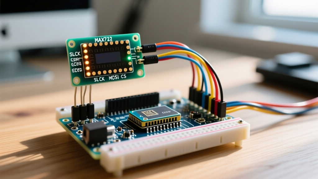
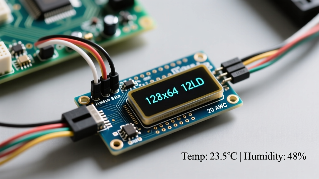
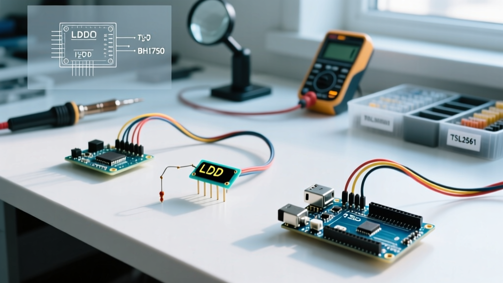
When engineers and advanced makers search for a standard sensor de temperatura arduino, they are typically met with isolated, single-component tutorials. However, real-world environmental monitoring, smart home nodes, and industrial logging require a multi-peripheral approach. Integrating a temperature sensor alongside an OLED display, an RTC (Real-Time Clock), and a relay module introduces complex hardware and software challenges. Bus capacitance limits, I2C address collisions, and power rail noise can silently corrupt your data or lock up your microcontroller.
In this 2026 guide, we move past basic wiring diagrams. We will engineer a robust multi-peripheral node using the Arduino Uno R4 WiFi, focusing on the electrical realities of the I2C bus, precise pull-up resistor calculations, and non-blocking firmware architecture.
Sensor Selection Matrix for Multi-Device Buses
Choosing the right temperature sensor dictates your bus topology. While 1-Wire sensors are popular, I2C sensors often integrate more predictably into multi-peripheral setups if managed correctly. Below is a comparison of the top three sensors used in advanced Arduino projects today.
| Sensor Model | Protocol | Accuracy (Typical) | 2026 Breakout Price | Multi-Peripheral Suitability |
|---|---|---|---|---|
| DS18B20 | 1-Wire | ±0.5°C | $2.50 - $4.00 | Moderate. Requires dedicated GPIO. Parasitic power mode often fails on noisy buses. |
| TMP117 | I2C | ±0.1°C | $4.50 - $6.00 | Excellent. Ultra-low power, programmable I2C addresses, minimal bus capacitance impact. |
| BME280 | I2C / SPI | ±0.5°C (Temp) | $8.00 - $11.00 | High. Combines temp/humidity/pressure. SPI mode recommended to free up I2C bus. |
For high-precision multi-peripheral setups, the Texas Instruments TMP117 is the superior choice. Its I2C address can be hardware-configured via the ADDR pin, preventing collisions with standard OLEDs (0x3C) and DS3231 RTCs (0x68).
The I2C Bottleneck: Bus Capacitance and Pull-Up Math
The most common failure mode in multi-peripheral Arduino setups is I2C bus lockup. According to the NXP I2C-bus specification, the maximum allowable bus capacitance ($C_b$) is 400 pF for standard and fast modes. Every wire, breadboard contact, and peripheral input pin adds parasitic capacitance. An SSD1306 OLED adds ~15 pF, a DS3231 adds ~10 pF, and long jumper wires can add 2-3 pF per centimeter.
Calculating the Correct Pull-Up Resistor
Most hobbyist tutorials blindly recommend 4.7kΩ pull-up resistors. In a multi-device setup operating at 400kHz (Fast Mode), 4.7kΩ is often too weak to pull the bus high before the next clock cycle, resulting in corrupted bytes and frozen displays.
The Pull-Up Formula:
$R_p(min) = \frac{V_{cc} - V_{ol}}{I_{ol}}$For a 5V Arduino Uno R4, assuming a maximum low-level output voltage ($V_{ol}$) of 0.4V and a sink current ($I_{ol}$) of 3mA:
$R_p(min) = \frac{5 - 0.4}{0.003} = 1533\Omega$
Actionable Advice: When wiring a TMP117, an OLED, and an RTC on the same I2C bus, discard the 4.7kΩ resistors. Use 2.2kΩ or even 1.5kΩ pull-up resistors tied to the 5V rail to ensure sharp rising edges on the SDA and SCL lines. Ensure your sensors are 5V tolerant, or use a bidirectional logic level shifter (like the BSS138) if mixing 3.3V sensors with a 5V bus.
Power Integrity: Mitigating Relay Switching Noise
Temperature sensors like the TMP117 are highly sensitive to voltage ripple. If your multi-peripheral setup includes a 5V relay module to control a heater or fan, the back-EMF and sudden current draws (often spiking to 70mA for 10ms) will cause voltage droops on the 5V rail. This droop can trigger a brownout reset on the Arduino or corrupt the I2C transaction mid-flight.
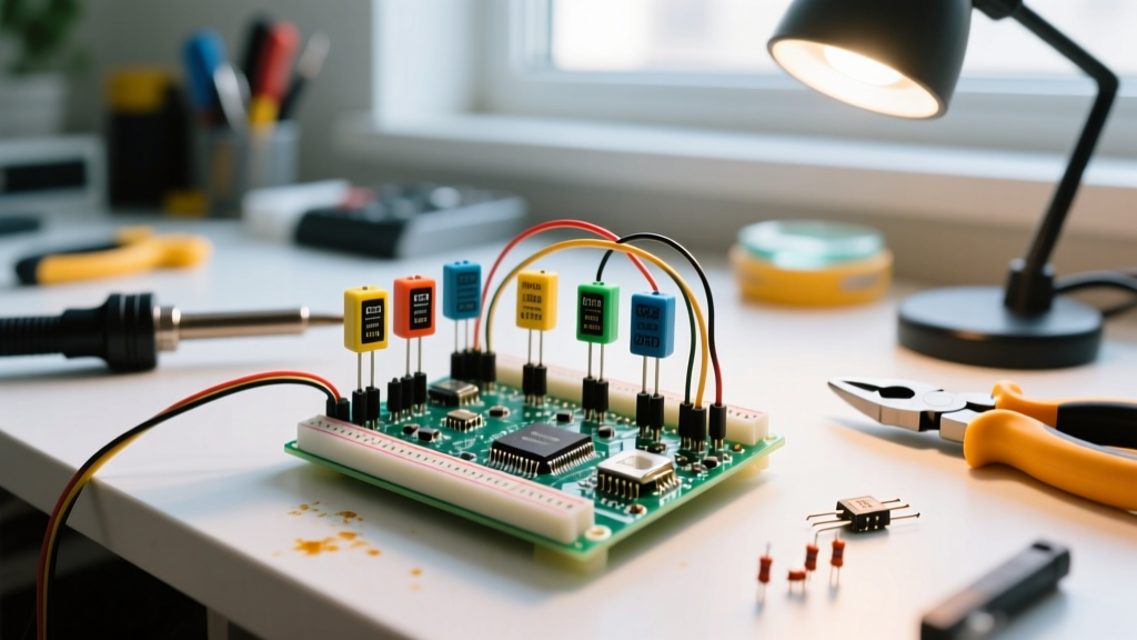
- Local Decoupling: Place a 100nF (0.1µF) ceramic capacitor directly across the VCC and GND pins of the temperature sensor breakout board.
- Bulk Capacitance: Add a 47µF to 100µF electrolytic capacitor near the relay module's power input to act as a local energy reservoir during coil energization.
- Opto-isolation: Use relay modules with built-in optocouplers (e.g., the Songle SRD-05VDC-SL-C based opto-isolated boards) and remove the JD-VCC jumper to separate the relay coil power from the Arduino logic power.
Software Architecture: Non-Blocking Sensor Polling
Using delay() in a multi-peripheral environment is a fatal flaw. A temperature conversion on a BME280 or DS18B20 can take up to 12ms. If you block the main loop, your OLED display refresh rate will stutter, and you may miss critical RTC interrupts or serial commands.
Leveraging the Arduino Wire Library Documentation best practices, implement a state-machine approach using millis().
Implementation Steps for Non-Blocking Reads
- Initialize Asynchronously: In your
setup(), configure the TMP117 for continuous conversion mode rather than one-shot mode. This pushes the conversion timing burden to the sensor's internal clock. - Time-Gate the I2C Bus: Create an interval variable (e.g.,
unsigned long lastTempRead = 0;). Only query the sensor every 2000ms. - Wire Request Limit: Keep I2C
Wire.requestFrom()calls out of interrupt service routines (ISRs). The Wire library relies on interrupts to function; calling it inside an ISR will cause a hard lockup. - Yield to the Display: Structure your
loop()so the OLED redraw function runs independently on a 100ms timer, pulling the latest cached temperature value from memory rather than querying the sensor directly.
Real-World Failure Modes & Troubleshooting
Even with perfect wiring, multi-peripheral setups exhibit unique edge cases. Here is a diagnostic matrix for common anomalies:
| Symptom | Probable Root Cause | Hardware / Software Fix |
|---|---|---|
| OLED flickers or shows garbage data exactly when the relay clicks. | I2C bus voltage droop or ground bounce exceeding logic thresholds. | Separate relay ground from logic ground; add 100µF bulk cap to relay VCC. |
| Sensor returns -127°C or NaN randomly. | I2C bus lockup due to missing ACK; SDA line stuck LOW. | Implement an I2C bus recovery routine (toggle SCL 9 times manually via GPIO). |
| Temperature reads 3°C higher than ambient. | Self-heating from OLED or voltage regulator bleeding into sensor thermal mass. | Mount sensor on a separate breakout via a 10cm twisted-pair cable away from the MCU. |
Final Integration Checklist
Before deploying your multi-peripheral node to the field, verify the following:
- [ ] I2C pull-up resistors are sized correctly for total bus capacitance (typically 2.2kΩ for 3+ devices).
- [ ] All I2C addresses are verified using an I2C Scanner sketch to ensure no overlaps (e.g., OLED at 0x3C, TMP117 at 0x48, RTC at 0x68).
- [ ] Decoupling capacitors (100nF) are placed within 5mm of every peripheral VCC pin.
- [ ] Firmware utilizes
millis()for all sensor polling, keeping the main loop execution time under 1ms.
By treating your sensor de temperatura arduino not as an isolated component, but as part of a holistic electrical ecosystem, you eliminate the intermittent bugs that plague multi-device projects. Proper bus management and power decoupling are the hallmarks of professional-grade embedded design.