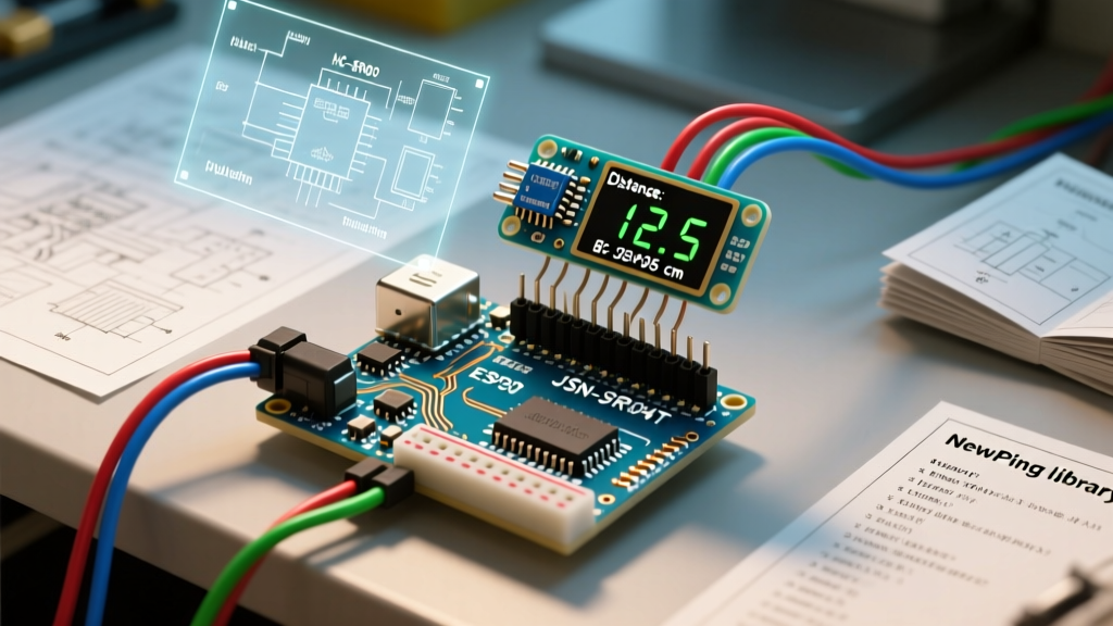

Integrating an ultrasonic to Arduino setup is a rite of passage for embedded systems engineers, but moving from a basic breadboard prototype to a robust, production-ready driver requires a deep understanding of both software libraries and hardware quirks. In 2026, the shift toward 3.3V logic architectures in mainstream boards like the Arduino Uno R4 Minima and Nano ESP32 has made legacy 5V sensor integration a primary failure point. Furthermore, acoustic multipath reflections and interrupt-blocking code can render a seemingly functional robot completely blind in dynamic environments.
This guide bypasses the superficial tutorials and dives directly into the library architectures, driver configurations, and electrical conditioning required to reliably interface HC-SR04, JSN-SR04T, and premium MaxBotix sensors with modern Arduino ecosystems.
The Native Bottleneck: Why pulseIn() Fails in Production
The default method for reading ultrasonic sensors relies on the native Arduino pulseIn() Reference function. While adequate for a single sensor on an empty loop, pulseIn() is inherently blocking. It halts the microcontroller's execution while waiting for the echo pin to transition from HIGH to LOW.
- The Timeout Trap: If a sensor is disconnected, or if the acoustic wave scatters into an anechoic void,
pulseIn()will wait for its default timeout of 1,000,000 microseconds (1 full second). In a 50Hz control loop for a balancing robot, a 1-second freeze guarantees a catastrophic crash. - The 30ms Rule: To cap the maximum range at 5 meters (the physical limit of most 40kHz transducers), you must manually set the timeout parameter to
30000microseconds. Even then, a 30ms blocking delay per sensor is unacceptable for multitasking frameworks like FreeRTOS.
NewPing: The Asynchronous Industry Standard
For standard 4-pin trigger/echo sensors, the NewPing library remains the undisputed champion. Unlike basic wrappers, NewPing leverages hardware timer interrupts (specifically Timer2 on AVR-based Arduinos) to achieve non-blocking, event-driven ultrasonic reading.
Event-Driven Reading via ping_timer()
By utilizing the ping_timer() method, the Arduino fires the trigger pulse and immediately returns to the main loop. When the echo is received (or times out), a hardware interrupt triggers a callback function. This allows you to poll up to 15 ultrasonic sensors without stalling the main MCU thread.
Expert Configuration Tip: When using NewPing's timer interrupts on an Arduino Uno or Mega, be aware that Timer2 controls the default PWM frequency on pins 3 and 11. If your motor driver relies on those specific pins for speed control, you will need to reassign your PWM outputs or switch to a software-based polling loop with a strict 35ms inter-ping delay to avoid acoustic crosstalk.
Hardware-Specific Driver Nuances
A library is only as good as the electrical signal it reads. Different ultrasonic transducers require vastly different driver configurations and hardware conditioning.
HC-SR04: The 3.3V Logic Trap
The classic HC-SR04 (currently priced around $2.50 in bulk) operates strictly at 5V. The Echo pin outputs a 5V HIGH signal. If you are interfacing this ultrasonic to Arduino boards featuring 3.3V logic (like the Nano ESP32 or Due), feeding a 5V signal into a 3.3V GPIO will permanently degrade or destroy the silicon.
The Fix: Your hardware design must include a voltage divider (e.g., a 4.7kΩ resistor in series with the Echo pin, and a 10kΩ resistor pulling it to ground) to step the 5V echo down to a safe ~3.2V.
JSN-SR04T V2.0: Waterproofing and Pull-Up Requirements
Priced around $9.00, the JSN-SR04T V2.0 separates the transducer from the driver board via a 2.5-meter cable, making it ideal for outdoor or wet environments. However, the V2.0 revision has a notorious quirk: the Echo pin can float if no target is detected, leading to phantom readings.
The Fix: A 47kΩ pull-up resistor connected between the Echo pin and the 5V rail is mandatory to stabilize the logic level. Additionally, the driver software must implement a blind-spot filter, discarding any readings below 20cm, as the physical separation of the transducer housing creates an acoustic dead zone at close range.
MaxBotix MB1010: Serial and Analog Parsing
For industrial applications where the $28.00 price tag of the MaxBotix Official Sensor Data MB1010 LV-MaxSonar-EZ1 is justified, you abandon the trigger/echo protocol entirely. The MB1010 outputs continuous RS232 serial data, PWM, and analog voltage.
Serial Driver Architecture: The sensor outputs ASCII data at 9600 baud in the format R255\r (where 'R' denotes the start, '255' is the distance in inches, and '\r' is the carriage return). Your Arduino driver must use a hardware UART or SoftwareSerial buffer, checking for the 'R' header, parsing the subsequent three bytes, and validating the carriage return to ensure data integrity.
Ultrasonic Driver Comparison Matrix
| Library / Method | Blocking? | Max Range | MCU Compatibility | Best Use Case |
|---|---|---|---|---|
Native pulseIn() |
Yes (High) | ~400cm | All | Simple, single-sensor educational projects |
| NewPing (Polling) | Yes (Low) | ~500cm | All | Multi-sensor arrays without timer conflicts |
| NewPing (Timer2) | No | ~500cm | AVR (Uno/Mega) | High-speed robotics, RTOS environments |
| Hardware UART Serial | No | ~760cm | All (Requires RX pin) | Industrial sensing, MaxBotix integration |
Advanced Signal Conditioning: Filtering Multipath Noise
Ultrasonic waves behave like light in a hall of mirrors. According to the physics of Ultrasonic Sensor Physics and Multipath, sound waves can bounce off a wall, hit the floor, and return to the receiver, reporting a distance much further than the actual target. This results in sudden, massive spikes in your data stream.
A standard Moving Average filter will fail here, as it will slowly drag your reported distance toward the phantom wall. Instead, implement a Median Filter with a window size of 5. By sorting the last 5 readings and selecting the middle value, you completely reject the multipath outliers without introducing the phase lag inherent in averaging filters.
Troubleshooting Acoustic Crosstalk & Power Rail Noise
When deploying an array of four or more HC-SR04 sensors on a single chassis, you will inevitably encounter acoustic crosstalk—where Sensor A listens to the echo generated by Sensor B.
Software Solution: Never fire multiple sensors simultaneously. Implement a round-robin state machine in your driver that fires Sensor 1, waits 35ms (allowing the acoustic wave to fully dissipate), fires Sensor 2, and so on.
Hardware Solution: Each ultrasonic transducer draws a sudden 15mA spike during the transmission burst. On a shared 5V rail, this causes voltage sags that reset the MCU or corrupt ADC readings. You must place a 100µF electrolytic capacitor and a 0.1µF ceramic decoupling capacitor directly across the VCC and GND pins of every single sensor to localize the current draw and maintain signal integrity.
By moving beyond blocking code and addressing the electrical realities of 3.3V logic and acoustic physics, your ultrasonic to Arduino integration will transition from a fragile prototype to a resilient, production-grade perception system.