
The Anatomy of an Arduino with Relay Module
Interfacing an Arduino with relay modules is a foundational milestone in embedded systems design, allowing low-voltage microcontrollers to switch high-power AC or DC loads. However, treating a mechanical relay as a simple digital switch without consulting its datasheet is a primary cause of field failures in DIY and prototyped industrial projects. Fried GPIO pins, unexplained microcontroller brownouts, and welded relay contacts almost always trace back to ignored datasheet parameters and misunderstood module circuitry.
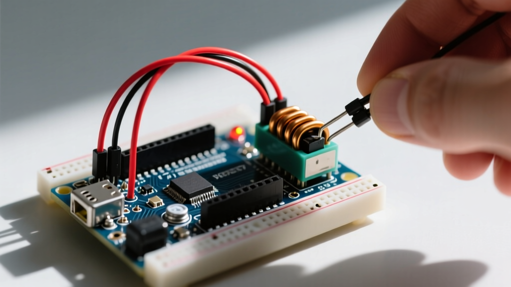
Before writing a single line of code to pull a GPIO pin HIGH, we must deconstruct the standard 5V relay module commonly paired with the Arduino Uno R3 or Nano. These modules are not just bare relays; they are complex switching circuits designed to bridge the gap between 5V logic and high-current coil requirements.
Core Components Beyond the Relay
A standard single-channel 5V relay module contains three critical support components that dictate how your Arduino interacts with the high-voltage side:
- The Optocoupler (PC817): Provides galvanic isolation between the Arduino's logic circuit and the relay's coil power supply. The internal LED typically requires 3mA to 5mA to trigger, easily sourced by an Arduino GPIO pin.
- The Switching Transistor (S8050 or 2N2222): The Arduino cannot drive a relay coil directly. A 5V relay coil typically draws 70mA to 90mA, far exceeding the 20mA safe continuous limit of an ATmega328P GPIO pin. The transistor acts as a current amplifier.
- The Flyback Diode (1N4148 or 1N4007): Placed in reverse bias across the relay coil, this diode clamps the inductive voltage spike generated when the magnetic field collapses, protecting the switching transistor and the microcontroller.
Decoding the Datasheet: Songle SRD-05VDC-SL-C
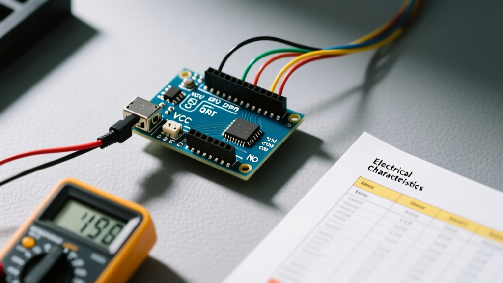
The vast majority of generic relay modules utilize the Songle SRD-05VDC-SL-C. While adequate for basic resistive loads, understanding its exact datasheet specifications is critical for predicting lifespan and preventing catastrophic failure. Below is a translation of the manufacturer's datasheet into real-world Arduino application parameters.
| Datasheet Parameter | Specified Value | Real-World Arduino Application Insight |
|---|---|---|
| Coil Voltage | 5VDC | Requires a stable 5V rail. If powered via Arduino USB, voltage drops below 4.5V can cause relay chatter. |
| Coil Resistance | ~70Ω | Draws ~71mA. Never wire the coil directly to the Arduino 5V pin without the module's transistor driver. |
| Pick-up Voltage | 75% of Nominal (3.75V) | The relay will engage at 3.75V, but operating near this threshold increases contact bounce and arcing. |
| Contact Rating (Resistive) | 10A @ 250VAC / 15A @ 125VAC | Strictly for heating elements or incandescent bulbs. Do not use for motors at these currents. |
| Electrical Life | 100,000 Operations | At full 10A load, expect 100k cycles. At 2A loads, lifespan extends to over 500,000 cycles. |
| Operate Time | ~10ms | Too slow for PWM or high-frequency switching. Use Solid State Relays (SSRs) for sub-millisecond timing. |
Critical Failure Modes and Edge Cases
When connecting an Arduino with relay circuits in the real world, the environment rarely matches the sterile conditions of a datasheet test bench. Here are the most common failure modes and how to engineer around them.
1. Contact Welding from Inductive Inrush
The most dangerous misinterpretation of the datasheet is the '10A Contact Rating'. This rating assumes a purely resistive load. When switching inductive loads like AC motors, solenoids, or compressors, the inrush current can be 6 to 10 times the steady-state running current. If you use a 10A relay to switch a 5A AC motor, the 30A+ inrush spike will cause severe arcing across the contacts. Over time, this arcing melts the silver-alloy contact pads, welding them together. The relay will fail in the 'CLOSED' position, leaving your high-voltage load permanently powered even when the Arduino commands it off.
Engineering Rule of Thumb: Always derate mechanical relays by at least 70% when switching inductive loads. A 10A relay should never switch a motor drawing more than 3A continuous. For heavy inductive loads, implement a snubber circuit (RC network) across the load terminals.
2. Back-EMF and Microcontroller Brownouts
When the transistor cuts power to the relay coil, the collapsing magnetic field generates a massive reverse voltage spike (inductive kickback). If the module's flyback diode is damaged, missing, or undersized, this spike couples back into the Arduino's 5V rail, causing immediate brownouts, corrupted EEPROM data, or permanent silicon damage. For a deeper understanding of the physics behind this phenomenon and diode selection, refer to the comprehensive breakdown of the flyback diode mechanism.
Step-by-Step: Wiring for True Opto-Isolation
Many hobbyists wire relay modules incorrectly, completely defeating the purpose of the onboard PC817 optocoupler. By default, most modules ship with a jumper connecting 'VCC' and 'JD-VCC'. This ties the relay coil power directly to the Arduino's 5V logic rail, meaning back-EMF noise travels straight into your microcontroller.
To achieve true galvanic isolation, follow this exact wiring sequence:
- Remove the Jumper: Pull the plastic jumper cap off the VCC and JD-VCC pins on the relay module.
- Power the Relay Coils: Connect an external 5V power supply's positive terminal to JD-VCC, and its ground to the module's GND (the one next to JD-VCC).
- Connect the Logic: Connect the Arduino's 5V pin to the module's VCC (the one next to the input pins).
- Connect Grounds: Connect the Arduino's GND to the module's GND (the one next to VCC/IN pins).
- Signal Wire: Connect your chosen Arduino GPIO (e.g., Pin 8) to the module's IN1.
This configuration ensures that the high-current coil switching and associated noise are entirely contained within the external power supply's loop, while the Arduino only sources the tiny ~3mA required to illuminate the optocoupler's internal LED.
Sourcing and Component Selection in 2026
The market for relay modules has matured significantly. When sourcing components for your next build, consider the trade-offs between standard mechanical modules and modern alternatives:
- Generic Songle Modules ($1.50 - $3.00): Adequate for basic home automation, lighting, and resistive heating elements. Expect high acoustic noise and mechanical wear.
- Premium Omron G5LE Modules ($4.50 - $7.00): Featuring superior contact materials and tighter coil tolerances. Highly recommended for critical applications where contact welding is a safety hazard. You can explore industrial-grade switching specifications via the Omron global relays hub.
- Solid State Relays / SSRs ($3.00 - $6.00): Modules like the Omron G3MB-202P use TRIACs or MOSFETs instead of moving parts. They offer zero acoustic noise, infinite electrical lifespan, and sub-millisecond switching. However, they generate heat and require heatsinks for loads exceeding 1A.
If you are driving multiple relays and want to bypass the standard module transistors in favor of a custom PCB design, utilizing a Darlington transistor array like the Texas Instruments ULN2003A provides built-in flyback diodes and can sink up to 500mA per channel, simplifying your schematic significantly.
FAQ: Common Interfacing Questions
Can I power a 5V relay module directly from the Arduino Uno's 5V pin?
Technically yes, but it is highly discouraged. A single relay coil draws ~71mA. If you use a 4-channel module and activate all relays simultaneously, you will draw nearly 300mA. If your Arduino is powered via USB, this approaches the limit of standard USB ports and the onboard linear regulator, leading to severe voltage sag and erratic MCU behavior. Always use an external 5V buck converter for multi-channel modules.
Why does my relay click rapidly when connected to a PWM pin?
Mechanical relays have an operate time of ~10ms and a release time of ~5ms. They physically cannot keep up with PWM frequencies (typically 490Hz or 980Hz on Arduino). The coil partially energizes and de-energizes, causing the contacts to chatter violently, which will destroy the relay in minutes. If you need dimming or speed control, you must use a MOSFET or an SSR, not a mechanical relay.