
The Anatomy of Arduino Servo Motor Control
Unlike stepper motors that rely on open-loop step counting, hobby servos utilize an internal potentiometer and a closed-loop feedback circuit to hold precise angular positions. This makes Arduino servo motor control a foundational skill for robotics, automated camera gimbals, and IoT actuator projects. However, moving from a simple blink sketch to reliably driving high-torque servos requires a deep understanding of Pulse Width Modulation (PWM) timing, current draw limitations, and I2C multiplexing.
In this comprehensive guide, we bypass the superficial tutorials and dive into the electrical engineering realities of driving servos with ATmega328P and ESP32 microcontrollers, covering everything from basic Servo.h implementations to scaling up with PCA9685 I2C drivers.
2026 Hardware Ecosystem: Selecting Your Actuator
Choosing the right servo prevents mechanical failure and electrical brownouts. Below is a comparison of the most common actuators used in DIY electronics today:
| Model | Stall Torque (at 6V) | Stall Current | Avg. Price | Best Use Case |
|---|---|---|---|---|
| TowerPro SG90 | 1.8 kg-cm | ~250 mA | $2.50 | Micro-robotics, lightweight camera pans, sensor sweeps. |
| TowerPro MG996R | 13.0 kg-cm | ~2.5 A | $8.00 | Robotic arms, RC vehicle steering, heavy latches. |
| DS3218 20KG Digital | 20.0 kg-cm | ~3.2 A | $16.00 | Heavy lifting, bipedal walking robots, high-stress joints. |
The Brownout Trap: Wiring High-Torque Servos
The most frequent point of failure in Arduino servo motor control projects is attempting to power an MG996R or DS3218 directly from the Arduino's 5V pin. The onboard linear voltage regulator on an Arduino Uno R3 can safely supply roughly 500mA total. When a high-torque servo starts moving under load, it can instantly draw 2.5A or more. This massive current spike causes the 5V rail to collapse (a brownout), triggering the ATmega328P's internal watchdog or brownout detection, resulting in a continuous reset loop.
Expert Rule of Thumb: Never power servos exceeding the SG90 class directly from the microcontroller's 5V pin. Always use an external power supply and establish a common ground.
The BEC / UBEC Wiring Solution
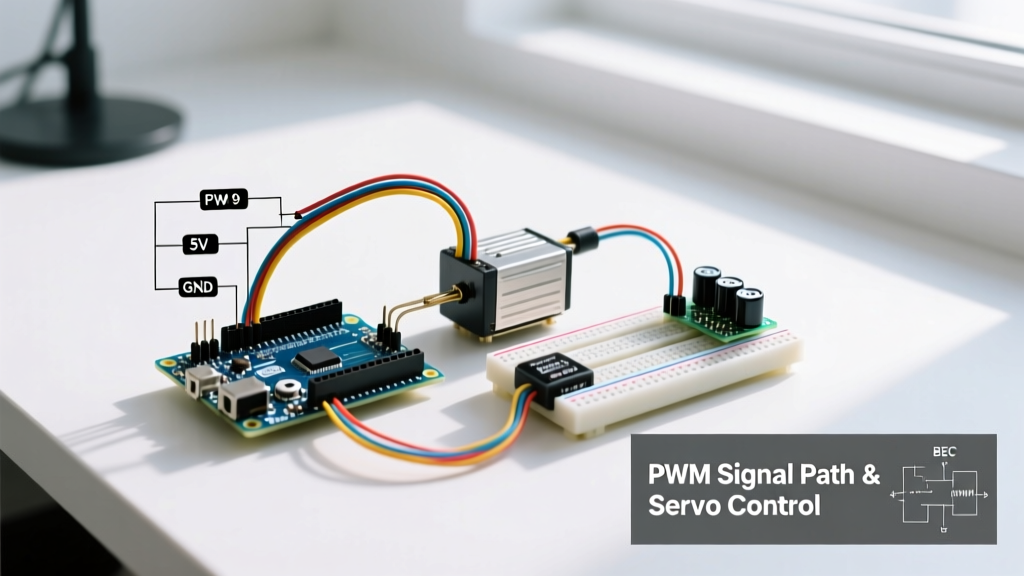
To safely wire a high-torque servo, you must use a UBEC (Universal Battery Eliminator Circuit) or a step-down buck converter (like the LM2596 module) to provide a dedicated 5V to 6V rail capable of delivering 3A to 5A.
- Power: Connect the UBEC 5V output to the servo's Red wire (VCC).
- Ground: Connect the UBEC GND to the servo's Brown/Black wire (GND).
- Signal: Connect the Arduino PWM Pin (e.g., Pin 9) to the servo's Orange/Yellow wire.
- Common Ground (Critical): You must connect a jumper wire from the Arduino's GND pin to the UBEC's GND. Without a shared ground reference, the PWM signal voltage is floating, and the servo will jitter violently or fail to respond.
For an in-depth look at RC servo current spikes and power requirements, refer to Pololu's comprehensive RC servo guide.
Under the Hood: 50Hz PWM Signal Theory
Hobby servos do not use standard analog voltages or serial data to determine position. They expect a 50Hz Pulse Width Modulation (PWM) signal. This means a new pulse is sent every 20 milliseconds (ms). The position of the servo horn is dictated entirely by the width of the high pulse within that 20ms window:
- 1.0 ms pulse: Commands the servo to 0° (fully counter-clockwise).
- 1.5 ms pulse: Commands the servo to 90° (center position).
- 2.0 ms pulse: Commands the servo to 180° (fully clockwise).
Note on Continuous Rotation Servos: If you are using a modified 360° continuous rotation servo (like the FS90R), the pulse width dictates speed and direction rather than absolute angle. A 1.5ms pulse stops the motor, 1.0ms spins it full speed in reverse, and 2.0ms spins it full speed forward.
Native Arduino Code: The Servo.h Library
For projects requiring 12 or fewer servos, the native Servo.h library is the standard approach. You can review the official Arduino Servo Library Documentation for API specifics. Below is an optimized sketch that maps an analog potentiometer to a servo while implementing a crucial power-saving and anti-jitter technique: detaching the servo when idle.
#include <Servo.h>

Servo myServo;
const int servoPin = 9;
const int potPin = A0;
const int jitterThreshold = 2; // Analog read tolerance

int currentAngle = 90;
int targetAngle = 90;

void setup() {
  myServo.attach(servoPin, 500, 2400); // Custom min/max pulse widths for full 180 sweep
  myServo.write(currentAngle);
  Serial.begin(9600);
}

void loop() {
  // Map 10-bit analog read (0-1023) to servo degrees (0-180)
  targetAngle = map(analogRead(potPin), 0, 1023, 0, 180);

  // Only update and power the servo if the physical movement is significant
  if (abs(targetAngle - currentAngle) > jitterThreshold) {
    myServo.attach(servoPin); // Re-engage PWM signal
    myServo.write(targetAngle);
    currentAngle = targetAngle;
    delay(15); // Allow servo time to physically reach the position

    // Optional: Detach to stop internal motor hum and save quiescent current
    // myServo.detach();
  }
  delay(20); // Match the 50Hz (20ms) refresh rate of standard servos
}
Timer Conflicts and Limitations
When you call myServo.attach() on an Arduino Uno, the library commandeers Timer1. This has a severe side effect: it disables hardware PWM (analogWrite()) on Pins 9 and 10. Furthermore, the ATmega328P simply does not have enough hardware timers to drive more than 12 servos natively. If your project requires a hexapod (18 servos) or a complex robotic hand, you must abandon Servo.h and move to an I2C PWM driver.
Scaling Up: PCA9685 I2C PWM Driver
The PCA9685 is a 16-channel, 12-bit PWM controller that communicates over I2C. It handles the strict 50Hz timing requirements in its own hardware registers, freeing up your microcontroller's timers and CPU cycles. The Adafruit PCA9685 PWM Servo Shield Guide provides excellent foundational wiring diagrams for this chip.
Wiring the PCA9685
- VCC (Logic): Connect to Arduino 5V (powers the I2C logic).
- GND: Connect to Arduino GND.
- SDA / SCL: Connect to A4/A5 (Uno) or dedicated SDA/SCL pins (ESP32/Mega).
- V+ (Servo Power): Connect to your external 5V/6V UBEC power supply. Do not connect this to the Arduino 5V pin.
I2C Addressing for Multi-Board Setups
The default I2C address for the PCA9685 is 0x40. If you are building a large-scale robot requiring 32 servos, you can chain two boards together. By soldering the address jumper pads (A0 through A5) on the back of the second PCB, you shift the I2C address. Bridging A0 changes the address to 0x41, allowing both boards to coexist on the same I2C bus without collisions.
Advanced Troubleshooting Matrix
Even with perfect code, real-world physics introduces electrical noise and mechanical binding. Use this matrix to diagnose common Arduino servo motor control failures.
| Symptom | Root Cause | Hardware / Software Solution |
|---|---|---|
| Violent Jittering | Noisy power rail or long, unshielded PWM signal wires picking up EMI. | Solder a 470µF to 1000µF electrolytic capacitor across the servo VCC/GND rails. Keep PWM wires under 12 inches, or use twisted-pair cabling. |
| Random Arduino Resets | Voltage brownout caused by servo stall current exceeding power supply limits. | Upgrade to a higher-amperage UBEC (e.g., 5A minimum). Ensure USB port isn't being used as the primary power source for the logic rail during heavy loads. |
| Servo Humming at Rest | Potentiometer deadband is too narrow; the servo is constantly micro-correcting. | Implement a software deadband (as shown in the code above) or call detach() once the target position is reached to cut the PWM signal. |
| Stripped Gears | Commanding angles beyond the physical hard-stops of the servo housing. | Calibrate your specific servo. Many '180-degree' servos physically stall at 5° and 175°. Limit your software mapping to map(val, 0, 1023, 10, 170). |
Detecting Stalls via Current Sensing
In advanced robotics, a stalled servo will draw maximum current, rapidly overheating the internal DC motor and melting the plastic gear teeth. To prevent this, integrate an INA219 I2C Current Sensor on the main servo power rail. By polling the INA219 in your Arduino loop, you can detect if the current draw spikes above 1.5A for more than 500ms. If this threshold is crossed, your code can instantly cut power via a logic-level MOSFET or command the servo to back off by 5 degrees, saving your hardware from catastrophic mechanical failure.
Conclusion
Mastering Arduino servo motor control requires looking past the basic write() function and respecting the electrical demands of closed-loop actuators. By providing robust external power via a UBEC, filtering EMI with capacitors, and scaling up with PCA9685 I2C drivers when necessary, you ensure your robotic joints and automated mechanisms operate smoothly, reliably, and without destroying your microcontroller.