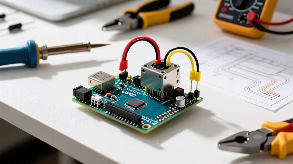

The Hidden Cost of Adding a Servo to Arduino in Complex Builds
Connecting a single micro servo to an Arduino Uno for a basic proof-of-concept is a rite of passage for every maker. You plug the signal wire into Pin 9, power it from the 5V rail, and watch it sweep. However, the moment you transition to a multi-peripheral setup—adding an I2C OLED display, an HC-SR04 ultrasonic sensor, and a relay module—that single servo becomes the catalyst for system-wide failure. The Arduino resets randomly, the LCD flickers, and the sensor returns garbage data.
This is not a software bug; it is a fundamental hardware power deficit. When routing the signal wire from your servo to Arduino microcontrollers, most beginners rely on the onboard 5V linear regulator. In 2026, with high-torque digital servos becoming cheaper and more accessible, understanding the electrical realities of multi-peripheral power distribution is no longer optional. This guide details exactly how to architect a robust power and signal network that prevents brownouts, eliminates PWM jitter, and protects your microcontroller from catastrophic back-EMF.
Current Draw Realities: Why the Onboard Regulator Fails
The Arduino Uno R3 (and its modern R4 Minima counterparts) features an onboard 5V voltage regulator. According to the official schematics, this regulator can handle an absolute maximum of 500mA, but the recommended continuous safe draw is closer to 200mA, especially if the board is powered via the barrel jack at 9V-12V. The onboard regulator must power the ATmega328P (or RA4M1), the USB-to-Serial converter, any connected I2C sensors, and your logic LEDs.
Now, consider the servo. A standard TowerPro SG90 draws roughly 200mA under normal operation, but its stall current spikes to 700mA. If you upgrade to a metal-gear MG996R for a robotic arm joint, the stall current surges to 2.5A. When a servo binds or starts under load, it pulls maximum current. If that current is routed through the Arduino's 5V pin, the onboard regulator instantly overheats, triggers its internal thermal shutdown, and drops the 5V rail to near zero. The microcontroller browns out, resets, and the peripheral network collapses.
Servo Power Consumption Matrix
When planning your multi-peripheral power budget, you must design for the stall current, not the no-load current. Below is a breakdown of common hobby servos and their electrical demands.
| Servo Model | Type / Gears | No-Load Current | Stall Current (Peak) | Recommended Power Supply |
|---|---|---|---|---|
| TowerPro SG90 | Analog / Plastic | ~200mA | 700mA | Arduino 5V (Max 1 only) |
| Futaba S3003 | Analog / Plastic | ~350mA | 1.2A | External 5V BEC (1.5A+) |
| HiTec HS-645MG | Analog / Metal | ~400mA | 1.8A | External 5V BEC (3A+) |
| DS3218 (20kg) | Digital / Metal | ~800mA | 3.5A | High-Power Buck (5A+) |
Note: Pricing for these servos ranges from $3 for the SG90 up to $22 for the DS3218 digital variant in 2026, but the hidden cost is always the external power infrastructure required to run them safely.
The Multi-Peripheral Power Architecture (Star Grounding)
To safely integrate a heavy-load servo to Arduino alongside sensitive I2C peripherals (like a BNO055 IMU or an SSD1306 OLED), you must isolate the high-current motor power from the low-current logic power. The industry-standard method for this is using an external BEC (Battery Eliminator Circuit) or a high-efficiency buck converter, wired in a Star Ground topology.
Step-by-Step Wiring Protocol
- Select a Buck Converter/BEC: For setups with 2-3 standard servos and multiple sensors, use a Pololu 5V, 5A Step-Down Voltage Regulator (D24V50F5). It costs around $14 and handles continuous 5A draws with minimal thermal throttling.
- Wire the High-Current Input: Connect your main battery pack (e.g., a 2S or 3S LiPo, or a 12V DC wall adapter) directly to the input terminals of the BEC. Do not route this main power through the Arduino's barrel jack.
- Establish the Star Ground: Connect the BEC's Ground (GND) output to the Arduino's GND pin. From this single Arduino GND pin, branch out to the GND pins of all your sensors, displays, and the servos. This ensures all peripherals share the exact same ground reference potential, preventing I2C communication errors caused by ground loops.
- Separate the 5V Rails: Connect the BEC's 5V output only to the red (VCC) wires of the servos. Do not connect the BEC's 5V to the Arduino's 5V pin. The Arduino should be powered via USB or its own dedicated low-current regulator.
- Route the PWM Signal: Connect the servo's signal wire (usually white or yellow) directly to an Arduino digital PWM pin. Because the grounds are tied together, the Arduino's 5V logic signal will be perfectly readable by the servo's internal controller.
Pro-Tip: The Decoupling Capacitor Rule
Always solder a 470µF to 1000µF electrolytic capacitor (rated for at least 10V) directly across the 5V and GND wires at the servo's connector. Digital servos draw current in high-frequency micro-bursts. This capacitor acts as a local energy reservoir, smoothing out voltage sags before they propagate back through the wiring harness and disrupt your I2C sensor bus.
Bypassing Timer Conflicts with the PCA9685
When you connect a servo to Arduino using the standard `Servo.h` library, the library hijacks Timer1 on the ATmega328P. In a multi-peripheral setup, this creates a massive headache: Timer1 is also responsible for hardware PWM on Pins 9 and 10. If you are trying to drive a DC motor via an L298N shield or dim an LED strip while sweeping a servo, you will find those pins outputting erratic signals.
Furthermore, if you need to control more than two or three servos, you will quickly exhaust the hardware timers on a standard Uno. The professional solution is to offload PWM generation to an I2C peripheral like the Adafruit 16-Channel PCA9685 PWM/Servo Shield.
Why the PCA9685 is Essential for Sensor Networks
- Zero Timer Conflicts: The PCA9685 generates its own hardware PWM signals internally. The Arduino only sends I2C commands, leaving all internal microcontroller timers free for sensor polling, interrupt service routines (ISRs), and motor control.
- Dedicated Power Terminals: The shield features screw terminals specifically designed for high-current servo power, complete with built-in reverse polarity protection and a dedicated 1000µF smoothing capacitor.
- I2C Address Flexibility: In complex builds involving multiple motor drivers or displays, I2C address collisions are common. The PCA9685 features address jumpers allowing you to shift its default
0x40address to any value up to0x7F.
Troubleshooting Jitter in Complex Sensor Networks
Even with a robust BEC and star-ground topology, makers frequently report servo jitter when ultrasonic sensors or relays activate. Here is how to diagnose and fix the edge cases:
1. Ultrasonic Sensor Noise Injection
The HC-SR04 ultrasonic sensor generates a 40kHz acoustic burst, which requires a sudden spike in current from the 5V rail. If your sensor and servo share a long, thin power wire (26 AWG or higher), the voltage drop from the ultrasonic burst will modulate the servo's power supply, causing the internal potentiometer to misread its position. Fix: Run dedicated 22 AWG power wires from the BEC to the servo, and keep sensor wiring under 15cm.
2. Relay Module Back-EMF
If your multi-peripheral setup includes a 5V relay module controlling a solenoid or AC load, the collapsing magnetic field of the relay coil generates a massive voltage spike (back-EMF) that travels back through the ground plane. This spike can corrupt the PWM signal traveling from the servo to Arduino pin. Fix: Ensure your relay module has an optocoupler isolation IC (like the PC817) and a flyback diode across the coil. Better yet, use a solid-state relay (SSR) for zero inductive kickback.
3. Wire Gauge and Connector Resistance
Dupont jumper wires are notorious for loose crimps and high resistance. A standard Dupont wire can drop 0.2V to 0.5V under a 1A load. A digital servo expecting 5.0V will behave erratically if it receives 4.4V. For any permanent or semi-permanent multi-peripheral rig, abandon Dupont cables for power delivery. Use JST-XH connectors or screw terminals with 22 AWG silicone wire, as recommended in comprehensive guides on powering electronics projects.
Conclusion
Successfully integrating a servo into a multi-peripheral Arduino environment requires shifting your mindset from 'signal logic' to 'power architecture.' By respecting the stall currents of modern actuaries, utilizing external buck converters, implementing star-ground topologies, and offloading PWM tasks to I2C drivers like the PCA9685, you eliminate the brownouts and jitter that plague amateur builds. Treat your power distribution with the same rigor as your C++ code, and your robotic assemblies will operate with flawless, industrial-grade reliability.