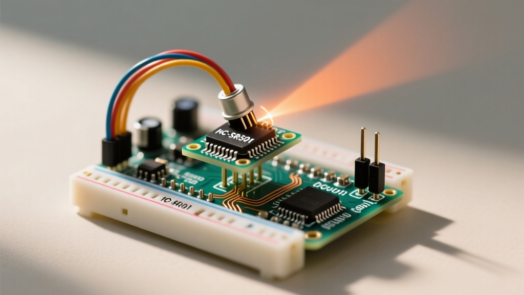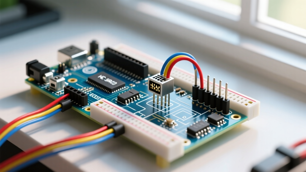

The Reality of the HC-SR04 in Modern Prototyping
When integrating an Arduino and ultrasonic sensor into a robotics or automation project, the HC-SR04 remains the undisputed king of budget-friendly distance measurement. Priced between $1.50 and $2.50 in 2026, it offers a theoretical range of 2cm to 400cm. However, its low cost comes with significant hardware and software quirks that frequently result in erratic readings, frozen microcontrollers, and phantom obstacles.
Troubleshooting the HC-SR04 requires moving beyond basic copy-paste tutorials. You must understand the acoustic physics of the 40kHz transducers, the electrical characteristics of the onboard MAX232 equivalent driver chips, and the blocking nature of standard Arduino timing functions. This guide provides a deep-dive diagnostic framework to isolate and resolve the most persistent failures encountered when pairing an Arduino and ultrasonic sensor.
Diagnostic Triage: Symptom-to-Solution Matrix
Before rewriting your code, map your specific failure mode using the diagnostic matrix below. This table isolates the root causes of the most common HC-SR04 anomalies.
| Symptom | Probable Root Cause | Hardware / Software Fix |
|---|---|---|
| Constant '0' or '0.00' output | Timeout exceeded; Echo pin never goes HIGH; object inside 2cm blind spot. | Verify wiring; increase pulseIn() timeout; move target beyond 2cm. |
| Random massive spikes (e.g., 3000cm) | Acoustic crosstalk from nearby sensors; power rail noise; floating Echo pin. | Add 0.1µF decoupling cap; stagger sensor firing; enable internal pull-ups. |
| Arduino freezes or reboots | VCC sag during 40kHz burst drawing >15mA; 5V Echo backfeeding 3.3V MCU. | Use dedicated 5V buck converter; implement logic level shifter or voltage divider. |
| Readings drift by 5-10% over time | Ambient temperature changes altering the speed of sound. | Integrate a DS18B20 temp sensor and apply software compensation formula. |
Hardware-Level Failure Modes and Fixes
1. The 3.3V Logic Level Mismatch
One of the most destructive mistakes when wiring an Arduino and ultrasonic sensor occurs when migrating from a 5V Arduino Uno to a 3.3V board like the Arduino Nano 33 IoT, ESP32, or Raspberry Pi Pico. The standard HC-SR04 requires a 5V VCC supply to generate the high-voltage acoustic burst. Consequently, its Echo pin outputs a 5V HIGH signal. Feeding 5V directly into a 3.3V GPIO pin will permanently degrade or destroy the microcontroller's silicon over time.
The Fix: You must step down the Echo signal. The most reliable, low-cost method is a resistor voltage divider. Connect a 1.2kΩ resistor in series with the Echo pin, and a 2.2kΩ resistor from the GPIO side of the first resistor to Ground. This divides the 5V signal down to a safe ~3.24V. Alternatively, upgrade to the HC-SR04P variant (typically $3.00), which features an onboard 3.3V voltage regulator and logic-level translation, allowing direct connection to modern 3.3V microcontrollers.
2. Power Rail Sag and Decoupling
During the 8-cycle, 40kHz transmission burst, the HC-SR04 can draw peak currents up to 15mA to 20mA. If your Arduino is powered via a long, thin USB cable or a shared breadboard rail with servos, this sudden current draw causes localized voltage sag. The onboard comparator circuitry misinterprets this sag, leading to premature Echo pin drops and truncated distance readings.
The Fix: Solder a 100µF electrolytic capacitor and a 0.1µF ceramic capacitor in parallel directly across the VCC and GND pins on the back of the HC-SR04 PCB. This local energy reservoir supplies the transient current demand without pulling down the main breadboard rail.
3. Acoustic Crosstalk and Beam Width
The HC-SR04 has a conical detection angle of approximately 30 degrees. In mobile robots using multiple sensors, sound waves can bounce off adjacent walls and trigger neighboring sensors, resulting in phantom obstacles. Furthermore, the transducers suffer from 'ringing'—mechanical vibration that persists for roughly 750µs after the burst, creating a strict 2cm blind spot.
The Fix: To narrow the beam angle from 30° to roughly 15°, slip a 20mm piece of 1/4-inch heat shrink tubing over each transducer and apply gentle heat. This physical waveguide dampens off-axis acoustic lobes. For multi-sensor arrays, never fire them simultaneously. Implement a strict 35ms delay between sensor triggers to allow acoustic reflections to dissipate completely.
Software-Level Troubleshooting
Escaping the pulseIn() Blocking Trap
The standard Arduino pulseIn() Reference outlines how to measure pulse width, but beginners often omit the timeout parameter. By default, pulseIn(echoPin, HIGH) will wait indefinitely for a pulse. If the ultrasonic wave scatters into an angled void and never returns, the Arduino halts all operations, freezing your entire control loop.
The Fix: Always define a timeout based on the maximum physical range of your application. Sound travels at roughly 343 meters per second. To measure up to 4 meters (8 meters round trip), the maximum pulse duration is about 23,300 microseconds. Set your timeout slightly higher to account for processing overhead:
duration = pulseIn(echoPin, HIGH, 30000);
This ensures the function returns a '0' after 30 milliseconds if no echo is detected, allowing your main loop to continue executing critical tasks like motor control.
Implementing Temperature Compensation
Many developers assume the speed of sound is a static 343 m/s. In reality, acoustic velocity is highly dependent on ambient temperature, governed by the formula: v = 331.4 + (0.6 × T), where T is temperature in Celsius. If your outdoor robot operates at 0°C, the speed of sound drops to 331.4 m/s. Using the standard 58µs per centimeter constant will introduce a cumulative error of nearly 7cm over a 2-meter distance.
The Fix: Integrate a cheap DS18B20 digital temperature sensor ($2.00) into your system. Sample the temperature every 5 seconds and dynamically update your distance calculation divisor. According to the Arduino Ping Example Documentation, standard math relies on static constants; replacing this with dynamic environmental variables is a hallmark of professional embedded engineering.
The Ultimate Fix: Median Filtering with NewPing
Even with perfect hardware wiring, the HC-SR04 is susceptible to acoustic multipath interference, yielding occasional 'jitter' or outlier readings. A simple moving average is insufficient because a single massive outlier (e.g., 3000cm) will skew the average for several cycles.
To achieve industrial-grade stability from a budget sensor, abandon manual ping() logic and adopt the NewPing Library Wiki methodology. NewPing handles the 10µs trigger pulse, manages timeouts natively, and crucially, includes a built-in median filter.
Pro-Tip for 2026 Projects: When using NewPing, utilize the
ping_median(iterations)method. Firing 5 to 7 rapid pings and taking the median value completely eliminates acoustic anomalies and electrical noise spikes without the computational overhead of complex Kalman filters. Note that 7 iterations take roughly 210ms; balance your iteration count against your robot's required control loop frequency.
When to Abandon the HC-SR04
Troubleshooting can only take you so far. If your application involves high-humidity environments, condensation, or requires sub-millimeter resolution, the HC-SR04 is the wrong tool. For outdoor or wet conditions, upgrade to the JSN-SR04T (approx. $4.50), which features a sealed, waterproof transducer on a 2.5-meter cable. For high-precision industrial bin-level measurement, bypass ultrasonic entirely and invest in a Time-of-Flight (ToF) LiDAR sensor like the TF-Luna ($12.00) or a MaxBotix MB1010 ($30.00), which offer vastly superior beam coherence and immunity to acoustic noise.
Summary Checklist for Reliable Integration
- Verify Logic Levels: Use a voltage divider for 3.3V MCUs or buy the HC-SR04P.
- Decouple Power: Add 100µF and 0.1µF capacitors across the sensor's VCC/GND.
- Set Timeouts: Never use
pulseIn()without a strict microsecond timeout limit. - Filter Data: Implement median filtering via the NewPing library to reject outliers.
- Compensate Environment: Apply temperature correction for outdoor or HVAC-heavy environments.
By addressing these specific electrical and acoustic edge cases, your Arduino and ultrasonic sensor setup will transition from a frustrating classroom toy into a robust, reliable perception module capable of handling real-world deployment.